5-42
When the control adjustment observation is complete, the control controller computes Rr (% maximum tilt per second) and Lr
(resting time in seconds). As shown below, the automatic tuning function uses the Gigl-Nichols equation to calculate gain.
It is strongly recommended that KPP be used for automatic tuning. The time required for the automatic tuning cycle depends on
the amount of process. A slowly changing PV requires a longer automatic tuning cycle time. When automatic tuning is
complete, the proportional, integral, and differential gain values are automatically updated to R+10, R+11, and R+12 at the
control table positions, respectively. The sample time for R+07 is also automatically updated. By measuring the PV response of
the closed-loop due to the output step change, the validity of the value generated by automatic tuning can be tested. The method
of performing this test is described in the manual tuning procedure section.
PID tuning
PI tuning
P=1.2×∆m/LrRr
P=0.9×∆m/LrRr
I=2.0×Lr
I=3.33×Lr
D=0.5×Lr
D=0
Sample rate =0.056×Lr
Sample rate =0.12×Lr
Δm = step change of output (10% = 0.1, 20% = 0.2)
If the automatic tuning error bit (bit 13 of control mode and alarm condition word R+06) is on, check that the PV value and SP
value are within 5% of the difference on the full scale (operating condition of the automatic tuning function). This bit is also
turned on when the output exceeds the limit of the range using the closed-loop method.
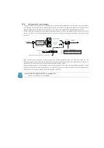
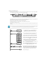
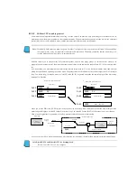
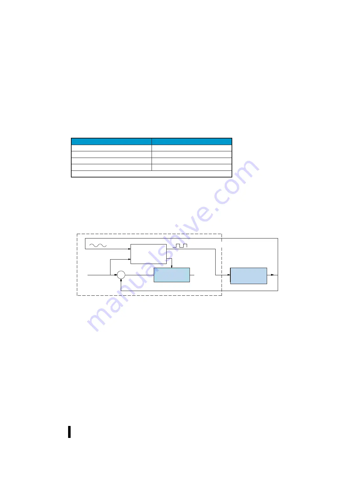
Automatic tuning conducted by the closed-loop -- The controller at the time of the automatic tuning cycle using the
closed-loop operates as shown below.
+
–
PLC
システム
応答
閉ループによる
自動チューニン
グ
ループ演算
製造プロセス
限界サイクル波
セットポイント値
偏差
制御出力
プロセス変数
プロセス変数
PLC System
Loop
calculation
Control
output
Set point value
Process variable
Deviation
Process variable
Manufacturing
process
Auto tuning by
close loop
Process variable
Response
Limit cycle wave
Summary of Contents for Kostac SJ-Ether Series
Page 1: ...English version of the KOSTAC SJ Ether series user s manual SJ ETHER USER M...
Page 12: ......
Page 13: ...1...
Page 14: ......
Page 88: ......
Page 89: ......
Page 113: ...3 24 Note Refer to 6 3 3 Module Assembly for connections and locks between modules...
Page 153: ......
Page 156: ...flashing OFF Not sent H W RX Green flashing Receiving H W OFF Not received H W...
Page 161: ...4 8...
Page 221: ......
Page 310: ...Chapter 7 Maintenance...
Page 311: ......


