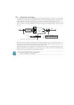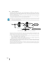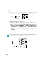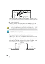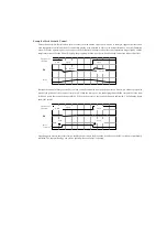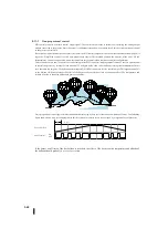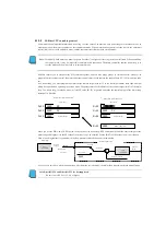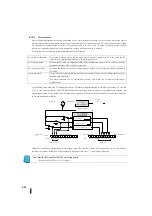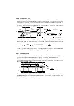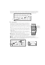
During automatic tuning, the control controller generates rectangular waves to the output. When the PV value crosses over (or
below) the SP value, the output waveform changes. Therefore, the frequency of the limit cycle is approximately proportional to
the collection of processes. From the PV response, the automatic tuning function calculates gain and sample time.
Automatically writes the result to the corresponding register in the control table.
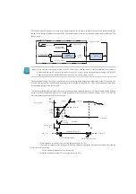
The following timing diagram shows where a closed-loop automatic tuning cycle occurs. The automatic tuning function
examines the direction of the PV offset from the SP. The automatic tuning function then controls the control output and changes
the step in the opposite direction when the limit value is reached. Each time the error signal (SP-PV) changes, the output
changes in the opposite direction. This is done in three cycles.
* Mmax = Control output value upper limit setting Mmin = Control output value lower limit setting
* This example is a direct-acting type. When the output is set in the reverse mode, the output is reversed.
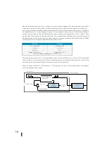
When the control adjustment observation is complete, the control controller calculates To (vibration period) and Xo (PV
amplitude). It uses these values to calculate Kpc (critical sensitivity) and Tpc (critical period). From these values, the control
controller automatic tuning function calculates PID (proportional integral differential) gain and sample rate using the
Gigra-Nichols equation shown below.
Kpc=4M/ (×X0) Tpc=0
M= output amplitude
PID tuning
PI tuning
P=0.45×Kpc
P=0.30×Kpc
I=0.60×Tpc
I=1.00×Tpc
D=0.10×Tpc
D=0
Sample rate = 0.014×Tpc
Sample rate = 0.03×Tpc
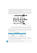
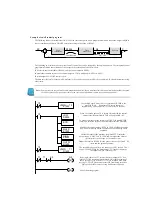
[Automatic tuning error]-When the automatic tuning error bit (control mode and alarm condition R+06) is ON, make sure that
the PV and SP values are within 5% of the full scale required by the automatic adjustment function. The closed-loop method is
used to turn on the bit when the output reaches the limit of the range.
Note :
If the PV changes rapidly, you must create a filter with the ladder circuit.
SP
PV
X
o
M
T
o
プロセス波
出力値
PID
サイクル
自動チューニングサイクル
自動チューニング開始
PID
パラメータの計算
自動チューニング終了
PID
サイクル
Process wave
PID cycle
Output value
Automatic tuning cycle
Start of automatic tuning
End of automatic tuning
PID cycle
Calculation of PID parameter
Summary of Contents for Kostac SJ-Ether Series
Page 1: ...English version of the KOSTAC SJ Ether series user s manual SJ ETHER USER M...
Page 12: ......
Page 13: ...1...
Page 14: ......
Page 88: ......
Page 89: ......
Page 113: ...3 24 Note Refer to 6 3 3 Module Assembly for connections and locks between modules...
Page 153: ......
Page 156: ...flashing OFF Not sent H W RX Green flashing Receiving H W OFF Not received H W...
Page 161: ...4 8...
Page 221: ......
Page 310: ...Chapter 7 Maintenance...
Page 311: ......

