5-46
5-11
Feedforward control
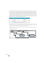
Feed forward control is a sophisticated standard closed-loop control. This is a reduction effect in measurement and a predictable
PID.
It is most useful for unstable control or sudden changes in set points. This is a good function, but it is best to adjust PID control
without feedforwarding, so use it only when it is necessary to further improve control performance.
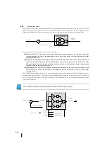
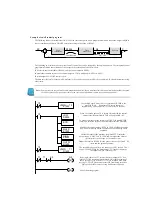
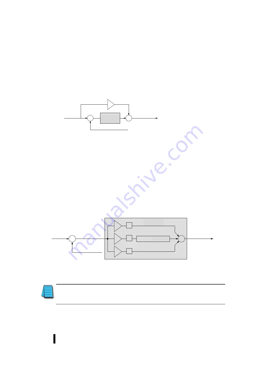
Refer to the diagram below for the control terminology of "feed forward".
The entering set-point value is sent before PID control and is summed to the output of the calculation result.
In the previous section about bias, we explained that the bias value is the operating point for the control output, and that when the
deviation varies around the zero point, the output varies centering on the bias value. When the set point changes, the output must
change to a new operating point because of the deviation. If there is disturbance, incorporate a new offset into the PID control. The
integrator (bias) is incremented or decremented until the deviation is eliminated. The bias finds a new point of operation.
Assume a sudden set-point change occurs (common in some applications). If you can quickly change the output to a new operating
point, first, and then quickly change the output to a new operating point, you can avoid most of the errors caused by the change in set
point. If you know how many operating points (bias values) should be selected from the previous test results after changing the set
point, you can manually change the output directly. This is called feed forward control. Feed-forward control has the following
advantages:
The SP-PV error can be suppressed as long as possible in anticipation of changes in set points or disturbances resulting in PID
control offsets.
If the feed forward is used correctly, the integration gain can be reduced. The reduction in integrated gain makes the control
system more stable.
As shown below, feed forward is very easy to use with the control controller. The bias value is in the dedicated PID parameter table
(R+04) and can be read/written by the user.
To change bias (point of operation), the required value must be written to R+04 in the ladder circuit. PID control reads the bias from
R+04 first and corrects the value based on the current integration calculation. Writes the result to R+04. This process creates a kind of
"transparent" bias value. The only thing to do with feed forward control is to write the correct value in a timely bias value.
Note :
When writing bias values, the ladder circuit must be designed to write values only once at the moment a new bias point
is generated. If the ladder circuit writes a bias value for all scans, the integration of PID control is effectively disabled.
+
–
+
k
f
+
セットポイント
ループ演算
制御出力
プロセス変数
フィードフォワード通路
+
–
+
P
I
D
+
+
k
p
k
i
k
d
R+04
XXXX
偏差
セットポイント
ループ演算
プロセス変数
制御出力
バイアス値
Loop
calculation
Control
output
Process variable
Set point
Feedforward path
Loop
calculation
Control
output
Bias value
Set point
Deviation
Process variable
Summary of Contents for Kostac SJ-Ether Series
Page 1: ...English version of the KOSTAC SJ Ether series user s manual SJ ETHER USER M...
Page 12: ......
Page 13: ...1...
Page 14: ......
Page 88: ......
Page 89: ......
Page 113: ...3 24 Note Refer to 6 3 3 Module Assembly for connections and locks between modules...
Page 153: ......
Page 156: ...flashing OFF Not sent H W RX Green flashing Receiving H W OFF Not received H W...
Page 161: ...4 8...
Page 221: ......
Page 310: ...Chapter 7 Maintenance...
Page 311: ......


