5-12-4
PV absolute value alarm
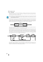
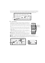
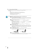
The PV absolute alarm consists of the upper limit alarm (two types) and the lower limit alarm (two types). As shown in the
figure below, the alarm condition is turned OFF as long as the PV value is within the range between the upper and lower alarm
limits. Alarms in the vicinity of safety zones are called High alarms and low alarms. When control is lost, the PV value first
exceeds any of these thresholds. Accordingly, the appropriate alarm threshold can be programmed into the control table
position shown to the right of the following. The data format is the same for PV and SP (12 or 15 bits). These alarm thresholds
must be set so that an early warning is issued if the process loses control.
As the process continues to lose control, the PV value ultimately exceeds the outer (upper or lower) alarm threshold and falls
into a range called High-high and low-low alarms. This threshold is also programmed using the control table registers listed
above. High-high or low-low alarms indicate dangerous conditions and inform the operator of the necessity of immediate
caution.
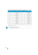
As shown on the right, the absolute PV alarm is notified using 4 bits of
PID mode and alarm status words in the control table .
It is strongly recommended that these bits be monitored by ladder logic.
Word Bit manipulation instructions enable you to use it easily. By using
KPP, the PID alarm is monitored.
Note: DirectSOFT4 and DirectSOFT5 are not supported.
Be sure to use KPP Ver1. 5.0.0 or higher.
PV
R+16
XXXX
R+15
XXXX
R+14
XXXX
R+13
XXXX
High-High
アラーム
High
アラーム
Low
アラーム
Low-Low
アラーム
ループテーブル
High-High
アラーム
High
アラーム
Low
アラーム
Low-Low
アラーム
0
1
3
4
5
6
7
8
9
10
11
12
13
14
15
2
High- High
アラーム
High
アラーム
Low
アラーム
Low- Low
アラーム
Bit
PID
モードとアラーム状態ワード:
R+06
High-High alarm
High alarm
Low alarm
alarm
High-High alarm
High alarm
Low alarm
Low- Low alarm
Loop table
High-High alarm
High alarm
Low alarm
Low- Low alarm
PID mode and alarm state word
Summary of Contents for Kostac SJ-Ether Series
Page 1: ...English version of the KOSTAC SJ Ether series user s manual SJ ETHER USER M...
Page 12: ......
Page 13: ...1...
Page 14: ......
Page 88: ......
Page 89: ......
Page 113: ...3 24 Note Refer to 6 3 3 Module Assembly for connections and locks between modules...
Page 153: ......
Page 156: ...flashing OFF Not sent H W RX Green flashing Receiving H W OFF Not received H W...
Page 161: ...4 8...
Page 221: ......
Page 310: ...Chapter 7 Maintenance...
Page 311: ......

