background image

5-54


5-12-5 

PV deviation alarm 

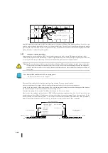
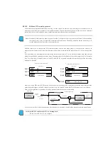
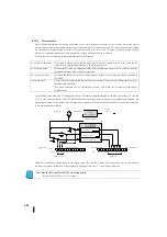
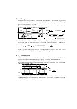
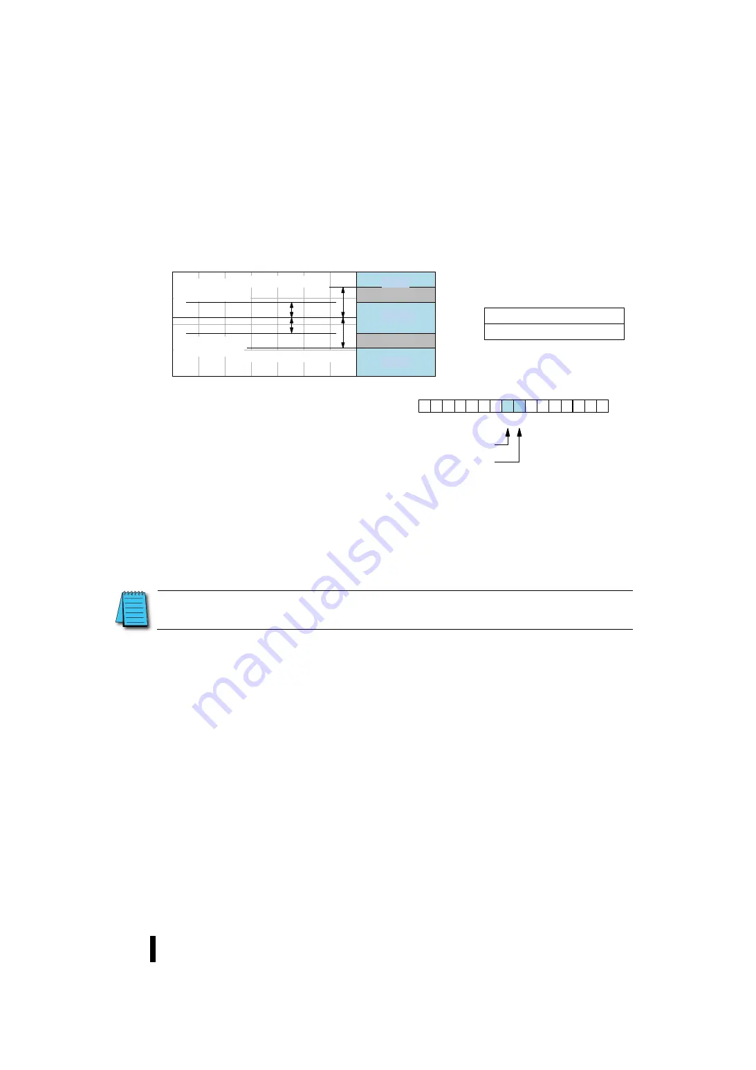
The PV deviation alarm monitors the PV deviation from the SP value. The deviation alarm has two programmable thresholds, 

each of which applies the same deviation above and below the configured SP value. In the figure below, the alarm with the 

lowest deviation is called the "deviation (yellow)" to show the caution status of PID control. The alarm with the larger deviation 

is  called  the  "deviation  (red)",  indicating  that  the  PID  control  error  condition  is  severe.  The  threshold  occupies  control 

parameter table positions R+17 and R+20 as shown below. 


These  thresholds  define  zones  of  variation  from  the  SP 

value.  The  green  zone  between  the  SP  values  indicates 

the  safety  condition  (no  alarm).  The  yellow  zone  is 

outside the green zone, and the red zone is further outside 

these zones. 

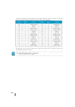
The PV deviation alarm is PID as shown to the right. 

The two bits of the mode and alarm position are reported. 

It is recommended to use a ladder circuit to monitor these 

bits.  It  is  easy  to  use  bit  manipulation  instructions  for 

words. In addition, you can monitor PID alarms by using KPP. 

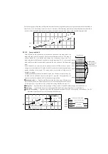
The PV deviation alarm can be enabled or disabled independently of other PV alarms using bit 13 of PID mode setting 1 R +00. 

The  alarm  hysteresis  function  operates  in  conjunction  with  both  the  deviation  alarm  and  the  absolute  value  alarm.  This  is 

explained at the end of this section. 


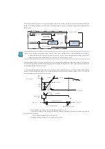
Note: DirectSOFT4 and DirectSOFT5 are not supported.


Be sure to use KPP Ver1. 5.0.0 or higher.


0

1

3

4

5

6

7

8

9

10

11

12

13

14

15

2

偏差アラーム(黄)


偏差アラーム(赤)


PID

モードとアラーム状態ワード:

R

06 

ビット


SP

Y

R+17

XXXX

R+20

XXXX

Y

偏差アラーム(赤)


偏差アラーム(黄)


偏差アラーム(黄)


偏差アラーム(赤)


ループテーブル


偏差アラーム(黄)


偏差アラーム(赤)


Red 

Deviation alarm    (Red) 

Deviation alarm   

(Yellow) 

Deviation alarm   

(Yellow) 

Deviation alarm    (Red) 

Red 

Yellow 

Yellow 

Green 

Loop table 

PID mode and alarm state word 

Deviation alarm    (Yellow) 

Deviation alarm    (Red) 

Deviation alarm    (Yellow) 

Deviation alarm    (Red) 

Bit 

Summary of Contents for Kostac SJ-Ether Series

Page 1: ...English version of the KOSTAC SJ Ether series user s manual SJ ETHER USER M...

Page 2: ...ay lead to serious accidents that could result in death or serious injury Note Indicates ignoring this indication may lead to injury or property damage Indicates general prohibition Indicates mandator...

Page 3: ...nd terminal blooks Failure to do so may cause damage Make sure the power supply voltage is same as those described in the specifications The failure could result in fire electric shock or malfunction...

Page 4: ...ilure to heed this warning may result in electric shock or failure Do not block the facility hole The temperature inside the main unit may increase resulting in fire or failure Maintenance Note Do not...

Page 5: ...s Modification of the part number described in the power supply module etc Deleted J 00AC and changed from J 01AC to C0 01AC Correction of errors in descriptions in the J 16CD1 16CD2 functional part S...

Page 6: ...d Hold power failure area The power failure retention time due to a large capacity capacitor is 4 hours Deleted P56 2 7 Self Diagnostic Function E099 causes were corrected P61 2 8 Switching of 3 CPU o...

Page 7: ...Details Additional explanation of the Port2 P 312 319 Appendix C SJ Ether New Addition Order Addition of explanation...

Page 8: ...of the main software is valid only when the normal functions of it do not work Exports of products For goods which need export permission certification or products that fall under technology the Fore...

Page 9: ...sible for the impact of the investment results regardless of the results in 3 Support Desk Technical inquiries Acceptance time 9 00 to 17 00 excluding Saturdays Sundays and public holidays For inquiri...

Page 10: ...U S Microsoft Corporation in the United States and other countries CC Link IF Filed Basic is a registered trademark of the CC Link Society EtherNet IP is a registered trademark of ODVA Open DeviceNet...

Page 11: ...1 Chapter 4 Specificion of communication 4 1 Chapter 5 PID Control 5 1 Chapter 6 System design 6 1 Chapter 7 Maintainance 7 1 Chapter 8 Appendix 8 1 Appendix A Licence of Software 8 2 Appendix B Other...

Page 12: ......

Page 13: ...1...

Page 14: ......

Page 15: ...ary 1 1 1 1Introduction 1 1 1 Accessory 1 2 1 1 2 For use 1 2 1 1 3 Application 1 4 1 1 4 Feature 1 5 1 2 Systems configuration 1 8 1 3 Peripherals layout 1 9 1 4 Linking system 1 10 1 4 1 Upper link...

Page 16: ...be sure to use products with the programming software KPP Ver 1 6 1 2 or later The following peripheral devices are available with this product Graphical Programmer etc Acceptability KPP Koyo PLC Prog...

Page 17: ...of the functions that can be used for this product model number are as follows Feature SJ DD1E D SJ DD2E D SJ DRE D SJ DD1EP D SJ DD2EP D SJ DREP D High speed counter pulse output EtherNet IP CC Link...

Page 18: ...C1 0 1 2 3 AD1V AD1I AD2V AD2I ACOM DA1V DA1I DA2V DA2I O U T I N SJ 12DD1E D KOSTAC Koyo V PWR RUN ERR PORT3 LNK ACT ETHER NET 100MBIT PORT1 TX1 RX1 RS 232C PORT2 RS 485 TX2 RX2 LG TREM RUN C0 0 1 2...

Page 19: ...repeated instructions and easy to use data processing ISG SG SG S000 I000 I001 Q000 I010 S002 Q000 M000 I001 I000 Q000 S001 PWR RUN ERR PORT3 LNK ACT ETHER NET 100MBIT PORT1 TX1 RX1 RS 232C PORT2 RS 4...

Page 20: ...mmer port Port1 and the general purpose communication port Port2 can be connected using non procedural serial communication Self diagnosis error is stored in the system using the history information s...

Page 21: ...ction PWR RUN ERR PORT3 LNK ACT ETHER NET 100MBIT PORT1 TX1 RX1 RS 232C PORT2 RS 485 TX2 RX2 LG TREM RUN C0 0 1 2 3 C1 0 1 2 3 AD1V AD1I AD2V AD2I ACOM DA1V DA1I DA2V DA2I O U T I N SJ 12DD1E D KOSTAC...

Page 22: ...e and extended I O module refer to the specifications in Chapter 3 and select and mount them PWR RUN ERR PORT3 LNK ACT ETHER NET 100MBIT PORT1 TX1 RX1 RS 232C PORT2 RS 485 TX2 RX2 LG TREM RUN C0 0 1 2...

Page 23: ...Koyo V GC A PLC PO RT PERIPHER AL RUN ERR AUM INH PRPHL CO MM o m r o n S Y A M A C C J 1 G C P U 1 3 PRO G RAMMABLE CPNTRO LLE R O PE N PO WE R TE ST N C N C A C 1 0 0 2 4 0 V IN P U T 1 0 0 B A S E...

Page 24: ...g from PLC to Computer Target memory Function memory program memory CPU operation mode etc Method When necessary from the computer master send the necessary message to the slave station slave station...

Page 25: ...A 50 60 Hz OUTP UT 24 V 1 3A G L N 24V 0 V J 01AC PORT 3 RX 3 TX 3 KOSTA C Koy o PORT 1 T X 1 R X 1 PORT 2 T X 2 R X 2 P WR R UN E RR RU N TE RM S J 0 2D D1 D C0 0 1 2 3 C1 4 5 6 7 C2 0 1 2 3 C3 4 5 I...

Page 26: ...nd modems can be connected and programmed and monitored remotely using the public network 6 Interface with programmers and programmable displays You can connect the PC programmer KPP for programming a...

Page 27: ...O transfer 2 33 2 6 1 CPU execution process 2 33 2 6 2 Scanning 2 34 2 6 3 I O transmittion 2 34 2 6 4 Batch transfer method 2 34 2 7 Self diagnosis function 2 35 2 8 CPU operation mode 2 37 2 8 1 CP...

Page 28: ...Data processing command 3 2 52 2 12 9 Special command for modules 2 54 2 12 10 Drun Ethernet communication command 2 54 2 12 11 IBox command 2 55 2 13 List of components 2 56 2 13 1 Part number naming...

Page 29: ...d low humidity IEC 60068 2 14 Test Na Temperature Changes Ambient humidity Ambient humidity 30 95 no condensation Ambient atmosphere No corrosive gases Environmental pollution level 2 UL 840 Vibration...

Page 30: ...nk relay GQ 2048 points GQ 0000 3777 Internal relay M 2048 points M 0000 3777 Stage S 1024 points S 0000 1777 Timer T 256 points T 000 377 Counter C 256 points C 000 377 Special relay SP 512 points SP...

Page 31: ...specification 2 5 I t e m Specification Basic Analog Diagnostic function software I O array check Program memory check Operation monitoring timer Communication error programmer port general purpose c...

Page 32: ...t M S Communication function Port3 EtherNet ports Transmission method CSMA CD carrier sense multiple access with collision detection Transmission rate Automatic 10 Mbps 100 Mbps switching 10 BASE 100...

Page 33: ...e occupies an area of eight points and the vacant number can be used as an internal relay Example Slot No 0 1 2 3 4 5 6 7 8 Power base Built in CPU I O Eight points Input Module Eight points Input Mod...

Page 34: ...fferent when the power supply of the PLC main unit is turned on the error is detected and the STOP mode is activated In this case select the I O array recorded in the system parameter area or the curr...

Page 35: ...R 406 00 40777 128 W S Stage S 0 1777 1024 points R 41000 41077 64 W T Timer T 0 377 256 points R 41100 41117 32 W C Counter C 0 377 256 points R 41140 41547 32 W SP Special relay SP 0 777 512 points...

Page 36: ...turning on off the output device connected to the output module as a result of executing the user program The program execution results are stored as output status in the output status memory of the...

Page 37: ...and NJMP commands The stage can be forcibly turned on off with the SET and RST commands Stages can be used as contact conditions such as LD commands There is no limit to the number of contacts used Wh...

Page 38: ...P is a special internal relay pre prepared in the system for convenience in creating user programs such as clocks and flags On user programs Special relay SP can only be used as contact conditions 8 R...

Page 39: ...be used as internal relays 11 Pointer P Pointer P is an indirectly designated register that indicates the register number in which the target data is stored in the program It works by using the data...

Page 40: ...ted with ON SP010 Contract SP011 RUN 0 Other than RUN 1 RUN ON when mode SW is in RUN mode SP012 TERM RUN SJ Ether unsupported Always OFF ON in terminal mode SJ Ether not always supported OFF in RUN m...

Page 41: ...53 Arithmetic error 0 No operation error 1 Calculation error present ON when calculation processing is impossible SP054 Communication instruction error 0 No error 1 Communication error ON at communica...

Page 42: ...a errors 1 Time of data error ON when BCD operation data is not BCD SP076 Read zero flag 0 Read value other than zero 1 When the read value is zero ON when data loaded by load command is 0 SP077 Contr...

Page 43: ...sent 0 Normal Error flag when Port3 is communicating Master Slave mode SP202 General purpose communication port 3 Number of connections exceeded 1 Maximum number of connections exceeded 0 Connectable...

Page 44: ...t4 Initializing THM RTD modules SP214 Slot5 Initializing THM RTD modules SP215 Slot6 Initializing THM RTD modules SP216 Slot7 Initializing THM RTD modules SP217 Slot8 Initializing THM RTD modules SP22...

Page 45: ...urrence flag 0 No abnormality normal 1 Abnormal This switch is turned on when an error related to CC Link IEF Basic communication is detected This bit is turned ON when there is a bit in the ON state...

Page 46: ...ning is not in progress 1 During shaft positioning ON during pulse output function positioning SP321 Axis 2 Positioning 0 Axial positioning is not in progress 1 During shaft positioning ON during puls...

Page 47: ...Chapter 2 Systems specification 2 21 Number N a m e C o n t e n t s Detailed SP346 SP777 Contract...

Page 48: ...Transmission Speed etc 8D01 R757 Setting of communication protocol completed Programmer Communication Port Port1 Set the setting completion code 0A00 R760 R777 Data register Data register None A speci...

Page 49: ...ea R7512 Initial value 108 R410 0 other than the above R7520 7527 Slot3 analogue I O area R7522 Initial value 110 R420 0 other than the above R7530 7537 Slot4 analogue I O area R7532 Initial value 118...

Page 50: ...eout setting Port1 MODBUS RTU communication Character to character timeout setting 0000 R7650 Non procedural communication Setting completed code General purpose communication port Port2 No procedure...

Page 51: ...de specified by the EtherNet IP protocol 0 R7704 EtherNet IP Lost Counter Counts the number of lost packets detected Sequence counter information is added to the Implicit message from the originator a...

Page 52: ...c communication function Each bit is assigned a function None R7732 CC Link IEF Basic Master station Calendar seconds The information is updated only while you are participating in the network 0 59 BC...

Page 53: ...the base slot number of the array error module 0000 R7755 Fatal anomaly code The error code is stored when a fatal error occurs 0000 R7756 Severe error code Stores the error code when a serious error...

Page 54: ...ted when a communication error occurs When ON retain the data OFF M472 Unused M743 Remote I O M NET communication Resuming When this relay is turned on communication is disconnected due to an error an...

Page 55: ...s Main program area Scanning is normally performed in the range from 0 to END command Main program area Stage or Ladder Programs Subprogram area From the END command to the last address it is usually...

Page 56: ...fic congestion monitoring timer of the operation processor System Parameter Setting Range I t e m Initial value unset value S e t t i n g r a n g e Program name Alphanumeric characters up to 8 digits...

Page 57: ...rea of the timer counter If the system parameters are changed from peripheral tools to the PLC in RUN mode set the system parameters to STOP mode once The system parameters that have been changed duri...

Page 58: ...ignment before turning off the power when turning on the power Normally when the system is determined set Array check to prevent malfunction when the module configuration changes 4 Power failure holdi...

Page 59: ...ation of hardware Array check of I O module Initialization of memory outside of blackout hold setting Input transmission Service of peripheral device Service of CPU Bus Renewal of clock and special re...

Page 60: ...forcibly turned ON OFF by programmer operation Process user program from 0 to END command Process of transferring the ON OFF status of the output function memory Q to the mounting output module Servi...

Page 61: ...the program Error Coding Contents of detection ERR LED Detection Timing CPU operation Abnormality Relay Error code register E104 MC writing error Programming When writing Suspension R7755 Causal facto...

Page 62: ...nsion SP47 R7755 Causal factors When I O array error is set the stored I O array registration data and I O implementation status are different Countermeasures If the sequence is intentionally changed...

Page 63: ...djust trial operation Program execution and I O transfer are repeated Address set monitor is available The mode selector switch is turned TERM TEST STOP This mode is used to debug programs and adjust...

Page 64: ...de is displayed in the PLC mode display at the bottom of the program display window In TEST RUN mode the debug tool is displayed as shown below If TEST mode is selected when PLC is in STOP mode TEST S...

Page 65: ...Executes PLC scan program from program 0 to END command only once and stops scanning the program 4 N scan Performs a scan as many times as you specify the PLC program This button can be used in TEST...

Page 66: ...operation mode is not guaranteed indeterminate In the no battery mode no errors occur when the battery voltage falls below the DC 2 5 V even if the battery is attached Even if the battery is attached...

Page 67: ...nce To view the history information select the PLC Diagnosis message in the KPP main menu 1 History information is cleared at the time of shipment In addition the history information can be cleared by...

Page 68: ...mple Type 1 Type 2 Type 3 Command Command Command Operand Operand Operand Operand Fixed number Function memory No Bit number Register number Program area address System memory number Decimal value BCD...

Page 69: ...1 Comparativ e agreement Contact instruction Logical operation start matching contact LDEQ 2 First word R Entire register range Second word R Entire register range P Entire range of indirect register...

Page 70: ...n SETDI 1 First word Limit to Q CPU implementation I O Direct coil off keeper operation RSTDI 1 Bit output instruction in the register area Bit outputting BOUT 2 1st word R Second word K bit number Bi...

Page 71: ...of the timer counter The last register in each register range cannot be specified because 2 2 word register is used 3 Duplicate use of ZOUT PD and SET RST commands for the same coil is prohibited The...

Page 72: ...start BSTART 2 End of stage block BEND 1 No operand Jump Start of jump GOTO 2 K 0 FFFF End of the jump GLBL 2 K 0 FFFF Repetition Repeated initiation FOR 2 R Entire register range K 0 9999 BCD End of...

Page 73: ...rs 32 bits OUTD 1 R Register total range 1 2 P Entire range of indirect registers Arbitrary bit OUTF 2 GI GQ I Q M K Bits 1 to 32 Direct 16 bits OUTDW 1 R Direct arbitrary bits 1 32 OUTDF 2 1st word Q...

Page 74: ...P Entire range of indirect registers 8 digits DIVD 2 R Register total range 1 2 P Entire range of indirect registers Arbitrary bit length 1 16 DIVF 2 1st word GI GQ I Q M S T C SP 2nd word K 1 16 Sta...

Page 75: ...F 8 digit constant BSUBC 2 K 0 FFFFFFFF BIN multiplicatio n 16 bits BMUL 3 1 R Entire register range P Entire range of indirect registers Stacked SBMUL 1 No operand Four digit constant BMULS 3 1 K 0 F...

Page 76: ...tacked SAND 1 No operand 8 digit constant ANDC 2 K 0 FFFFFFFF Logical sum 16 bits ORW 1 R Entire register range P Entire range of indirect registers 32 bits ORD 1 R Register total range 1 P Entire ran...

Page 77: ...total range 1 P Entire range of indirect registers Arbitrary bit length 1 to 32 XORF 2 1st word GI GQ I Q M S T C SP 2nd word K 1 32 Stacked SXOR 1 No operand 8 digit constant XORC 1 K 0 FFFFFFFF Note...

Page 78: ...CDCPL 1 BIN code conversion BIN 1 BCD code conversion BCD 1 GRAY coding GRAY 1 Decoding DECO 1 Encoding ENCO 1 7 segment decoding SEG 1 Right shifted SHFR 2 R Entire register range K Bits 1 to 32 Left...

Page 79: ...K 0 FFFF Multi byte data retrieval instruction BSRCH 2 R Data class classification CLASS 2 R K 0 FFFF With pointer Table Processing Pointer addition drawer TTD 2 R Pointer subtraction RFB 2 R Pop up d...

Page 80: ...range 2 12 10 Drums EtherNet Communication command Classification Order Numb er of words Operand Telecommunicati on Module Timer drum DRUM 52 C Time event operated drum EDRUM 68 C Masked time event O...

Page 81: ...overtime binary FILTERB 64 Analog scale binary conversion ANSCLB 24 High Low Alarm Binary BCD HILOAL 63 Filter overtime BCD FILTER 67 Analog scale BCD ANSCL 26 Computati on 16 bit BCD Decimal Real Nu...

Page 82: ...any number Series symbol No of points Indicate I O number of points to be provided to outside by 2 digits Type of I O N Input T Output C Input and Output S Select I O The same kind module classificati...

Page 83: ...provided to outside by number Type of I O AD Analog Input Number of points Indicates the number of I O points to be provided to outside by number Module type 1 Electric current type 2 Voltage type Ty...

Page 84: ...AC 17 240 V SSR 0 3 A 100 g Eight points J 08TR Relay 1 A 110 g Four points J 04TRS Relay SPDT 7 A 125 g In Out Capab ilities 4 points 4 points J 08CDR Enter DC 12 24 V sink source Output Relay 24 VD...

Page 85: ...eight Remarks 16 bit resolution Peripheral PC programmer KPP On off line programming monitor and printout Operation display panel S 10D Change of monitor and T C setting Message display 160 g Simplifi...

Page 86: ...Chapter 2 Systems specification 2 60 2 14 Dimensional outline drawing S J E t h e r U p p e r Unit mm S J E t h e r F r o n t M4 M4 Unit mm Attachment hole for M4 Attachment hole for M4...

Page 87: ...Chapter 2 Systems specification 2 61 Ether Aspects Unit mm A IO 1 8 7 6 5 4 3 2 115 4 142 4 169 4 304 4 277 4 250 4 223 4 196 4 Number of extended I O module 1 2 3 4 5 6 7 8...

Page 88: ......

Page 89: ......

Page 90: ...ND3 3 30 3 3 6 8 point AC 100 120 V input module J 08NA 3 31 3 3 7 8 point output module J 08TD1 3 32 3 3 8 8 point output module J 08TD2 3 33 3 3 9 16 point output module J 16TD1 3 34 3 3 10 16 point...

Page 91: ...built in module 3 58 3 6 2 Analog data input output register with built in CPU 3 59 3 6 3 Register setting for analog data with built in CPU 3 60 3 6 4 Register for setting optional analog module 3 6...

Page 92: ...voltage DC 24 V Required current Max 120 mA 3 1 3 Common hardware specifications 1 LED PWR Green This lamp lights when the power is turned on RUN Green Lights during program execution ERR Red This lam...

Page 93: ...e memory even if it is not connected to an external power source 5 I O terminal block connector A removable European terminal block connector with I O terminals 6 Power input terminal block lower A re...

Page 94: ...ampere 0 2 mA Maximum input current 7 mA 26 4 VDC Voltage drop on DC 0 5 V 0 1 A Input impedance 3 9 k 24 VDC Maximum leakage current 0 1 mA DC 30 V On voltage current DC 19 V 4 5 mA Voltage drop on D...

Page 95: ...VCC GND 3 3V V Y1 COM 24VDC 5 27VDC Internal Module circuitry Equivalent circuit D C In Capabilities Input I0 I7 D C Out Capabilities Output Q0 Q5 VCC GND 3 3V 24VDC INPUT COM Internal Module circuit...

Page 96: ...V Max output current 0 1 A point 0 6 A C0 Input current Typ 6 5 mA 24 VDC Minimum output ampere 0 2 mA Maximum input current 7 mA 26 4 VDC Voltage drop on DC 0 5 V 0 1 A Input impedance 3 9 k 24 VDC...

Page 97: ...3 8 Equivalent circuit D C In Capabilities Input I0 I7 D C Out Capabilities Output Q0 Q5 VCC GND 3 3V V Y1 0V 24VDC Internal Module circuitry VCC GND 3 3V 24VDC INPUT COM Internal Module circuitry...

Page 98: ...ating voltage range DC 21 6 26 4 V AC frequency 47 63 Hz Input current Typ 6 5 mA 24 VDC Maximum current 1 0 A point 4 0 A C2 and 2 0 A C3 Maximum input current 7 mA 26 4 VDC Minimum load current 5 mA...

Page 99: ...Input I0 I7 Relay output Loading condition Life DC 30 V 3 A resistive loads 100 000 cycle or more DC 30 V 3 A induced loading 50 000 cycle or more AC250 V 3 A resistive load 100 000 cycle or more AC2...

Page 100: ...akage current 0 1 mA DC 30 V On voltage current DC 19 V 4 5 mA Voltage drop on DC 0 5 V 0 1 A OFF VOLTAGE CURRENT DC 2 V 0 5mA Maximum rush current 150 mA 10 ms Response Hours OFF ON Typ 3 s Max 5 s R...

Page 101: ...2 VCC GND 3 3V V Y1 COM 24VDC 5 27VDC Internal Module circuitry Equivalent circuit D C In Capabilities Input I0 I3 D C Out Capabilities Output Q0 Q3 VCC GND 3 3V 24VDC INPUT COM Internal Module circui...

Page 102: ...s deviation during noise test 20 of full scale 20 of full scale I t e m Analogue output specification Voltage output selection Current output selection Number of output Up to 2 channels depending on t...

Page 103: ...r Internal Module Circuitry 10K 10K A D Converter ADxI 0V Transmitter P S Current Transmitter Internal Module Circuitry 125 A na lo g ou tp ut Voltage output selection Current output selection DAxV 0V...

Page 104: ...kage current 0 1 mA DC 30 V On voltage current DC 19 V 4 5 mA Voltage drop on DC 0 5 V 0 1 A OFF VOLTAGE CURRENT DC 2 V 0 5mA Maximum rush current 150 mA 10 ms Resp onse Hour s OFF ON Typ 3 s Max 5 s...

Page 105: ...3 16 Equivalent circuit D C In Capabilities Input I0 I3 D C Out Capabilities Output Q0 Q3 VCC GND 3 3V V Y1 0V 24VDC Internal Module circuitry VCC GND 3 3V 24VDC INPUT COM Internal Module circuitry...

Page 106: ...s deviation during noise test 20 of full scale 20 of full scale I t e m Analogue output specification Voltage output selection Current output selection Number of output Up to 2 channels depending on t...

Page 107: ...r Internal Module Circuitry 10K 10K A D Converter ADxI 0V Transmitter P S Current Transmitter Internal Module Circuitry 125 A na lo g ou tp ut Voltage output selection Current output selection DAxV 0V...

Page 108: ...pedance 3 9 k 24 VDC Maximum rush current 3 A 10 ms On voltage current DC 19 V 4 5 mA Resp onse Hours OFF ON 15ms OFF VOLTAGE CURRENT DC 2 V 0 5mA On and off 15ms Resp onse Hour s OFF ON Typ 3 s Max 5...

Page 109: ...Input I0 I3 Relay output Loading condition Life DC 30 V 3 A resistive loads 100 000 cycle or more DC 30 V 3 A induced loading 50 000 cycle or more AC250 V 3 A resistive load 100 000 cycle or more AC2...

Page 110: ...s deviation during noise test 20 of full scale 20 of full scale I t e m Analogue output specification Voltage output selection Current output selection Number of output Up to 2 channels depending on t...

Page 111: ...r Internal Module Circuitry 10K 10K A D Converter ADxI 0V Transmitter P S Current Transmitter Internal Module Circuitry 125 A na lo g ou tp ut Voltage output selection Current output selection DAxV 0V...

Page 112: ...ped terminal 1 25 Allowable tightening torque 0 6 Nm Compliant DIN rail TH35Fe TH35Al 1 DC 24 V power supply terminal This is the DC 24 V power supply for supplying to the CPU module 2 Frame ground te...

Page 113: ...3 24 Note Refer to 6 3 3 Module Assembly for connections and locks between modules...

Page 114: ...insulated In order to conform to IEC UL 61010 2 201 when the output is connected to a circuit that exceeds the 30 V insert a transformer with basic insulation or more at the front of the relay output...

Page 115: ...J 04TRS Relay DC 24 V AC 240 V 7 A point 7 A common 4 points 8 points Input output J 08CDR IN Sink Source DC 12 24 V 4 Point 8 Point OUT relay DC 24 V AC 240 V 1 A point 4 A common 4 Point 8 Point J 1...

Page 116: ...ped terminal Ferrule I2 10 mm d1 1 mm d2 2 6 mm d1 s1 s1 1 3 mm Allowable tightening torque 0 22 Nm Terminal width 2 6 mm 3 Extended module connection terminal side When connecting to the CPU module a...

Page 117: ...8 26 4 V Peak voltage DC 26 4 V Input current 5 mA DC 24 V Maximum input current 7 mA DC 26 4 V Required current at main power supply side Max 30 mA On voltage current DC 8 0 V 1 4 mA OFF VOLTAGE CURR...

Page 118: ...5 5 V Peak voltage DC 5 5 V Input current 5 5 mA DC 5 V Maximum input current 7 5 mA DC 5 5 V Required current at main power supply side Max 30 mA On voltage current DC 2 2 V 1 4 mA OFF VOLTAGE CURRE...

Page 119: ...V Input current 4 mA DC 24 V Maximum input current 5 mA DC 26 4 V Required current at main power supply side Max 40 mA On voltage current DC 19 0 V 3 5 mA OFF VOLTAGE CURRENT DC 7 0 V 0 5 mA Input im...

Page 120: ...ent 8 5 mA AC 100 V 50 Hz 10 mA AC 100 V 60 Hz Maximum input current 16 mA AC144 V Required current at main power supply side Max 30 mA On voltage current AC 70 V 5 mA OFF VOLTAGE CURRENT AC 20 V 2 mA...

Page 121: ...current 0 3 A point 1 2 A common Maximum leakage current 0 1 mA DC 30 V Maximum rush current 1 A 10 ms Minimum load current 0 5 mA External power supply DC 24 V 10 max 15 mA Required current at main...

Page 122: ...FET Voltage drop on DC 1 5 V 0 3 A Max output current 0 3 A point 1 2 A common Maximum leakage current 0 1 mA DC 30 V Maximum rush current 1 A 10 ms Minimum load current 0 5 mA Required current at mai...

Page 123: ...point 0 8 A common Maximum leakage current 0 1 mA DC30 V Maximum rush current 150 mA 10 ms Minimum load current 0 2 mA External power supply DC 24 V 10 max 100 mA Required current at main power supply...

Page 124: ...0 1 A Max output current 0 1 A point 0 8 A common Maximum leakage current 0 1 mA DC 30 V Maximum rush current 150 mA 10 ms Minimum load current 0 2 mA Required current at main power supply side Max 80...

Page 125: ...than AC 3 0 V 0 1 A Max output current 0 3 A point 1 2 A common Maximum leakage current 4 mA AC288 V Maximum rush current 10 A 10 ms Minimum load current 10 mA Required current at main power supply si...

Page 126: ...int 4 A common Maximum leakage current 0 1 mA AC 264 V Maximum rush current 3 A 10 ms Minimum load current 5 mA DC 5 V Required current at main power supply side Max 100 mA Responses times OFF ON Max...

Page 127: ...V Maximum rush current 12 A Minimum load current 100 mA DC 5 V Required current at main power supply side Max 100 mA Responses times OFF ON Up to 15 ms On and off Up to 15 ms Fuse None Loading condit...

Page 128: ...0 8 26 4V Peak voltage DC 26 4V Input current 5mA DC 24V Maximum input current 7mA DC 26 4V On voltage current DC 8 0V 1 4mA OFF VOLTAGE CURRENT DC 3 0V 0 5mA Input impedance 4 7k DC 24V Responses tim...

Page 129: ...rrent 1 A point 4 A common Maximum leakage current 0 1 mA AC 264 V Maximum rush current 3 A 10ms Minimum load current 5 mA DC 5 V Responses times OFF ON Up to 15 ms On and off Up to 15 ms Fuse None I...

Page 130: ...k voltage DC 26 4 V Input current 4 mA DC 24 V Maximum input current 5 mA DC 26 4 V On voltage current DC 19 0 V 3 5 mA OFF VOLTAGE CURRENT DC 7 0 V 0 5 mA Input impedance 6 8 k DC 24 V Responses time...

Page 131: ...0 1 A Max output current 0 1 A point 0 8 A common Maximum leakage current 0 1 mA DC30 V Maximum rush current 150 mA 10ms Minimum load current 0 2 mA External power supply DC 24 V 10 max 50 mA Respons...

Page 132: ...Peak voltage DC 26 4 V Input current 4 mA DC 24V Maximum input current 5 mA DC 26 4V On voltage current DC 19 0 V 3 5 mA OFF VOLTAGE CURRENT DC 7 0 V 0 5 mA Input impedance 6 8 k DC 24 V Responses tim...

Page 133: ...oltage range DC 9 6 30 V Peak voltage DC 30 V Output type PNP open collector Voltage drop on DC 0 6 V 0 1 A Max output current 0 1 A point 0 8 A common Maximum leakage current 0 1 mA DC 30 V Maximum r...

Page 134: ...f the range temperature change Linearity error Maximum 3 counts Input stability and repeatability Maximum 2 counts Full scale calibration Maximum 8 counts Offset calibration error Maximum 8 counts Max...

Page 135: ...ithin 100 ms Accuracy of temperature Max 75 PPM Maximum error 0 5 of the range temperature change Linearity error Maximum 3 counts Input stability and repeatability Maximum 2 counts Full scale calibra...

Page 136: ...Accuracy of temperature Max 75 PPM Max Crosstalk 50 per 60 Hz in DCs 72dB 1LSB Linearity error Max 4 LSB full scale 0 1 Output stability and reproducibility 2 LSB after 10 min warm up period Output r...

Page 137: ...Range maximum 0 2 Accuracy of temperature Max 75 PPM Max Crosstalk 50 per 60 Hz in DCs 72dB 1LSB Linearity error Max 4 LSB full scale 0 1 Output stability and reproducibility 2 LSB after 10 min warm...

Page 138: ...4 20mA Out CH1 0V CH2 0V CH3 0V CH4 0V CH1 0V CH2 0V 0V 24V INPUT OUTPUT N C N C N C N C N C N C 24 VDC 2 4 20mA 2 4 20mA 3 4 20mA 4 4 20mA All 0V are connected inside 2 wiring 4 20mA Signal source 2...

Page 139: ...etting time Maximum 0 2 ms minimum 5 s full scale range All channel update cycles 20ms Maximum overload Protect with open circuit Output protection Limited to 20 mA or less C0 4 AD2DA 1 Analogue Input...

Page 140: ...put Module C0 4 AD2DA 2 0 V C0 4AD2DA 2 0 10V CH1 0V CH2 0V CH3 0V CH4 0V CH1 0V CH2 0V 0V 24V INPUT OUTPUT N C N C N C N C N C N C 24 VDC Voltage generator Voltage generator Voltage generator Voltage...

Page 141: ...rosstalk at DC Maximum 2 counts C0 4 AD2DA 2 Analogue Output Specifications Number of output 2 Output voltage range 0 10 V Resolution 12 bit 2 44 mV counting Output type Max 10 V Source 1 Common Outpu...

Page 142: ...65 to 2320 149 to 4208 F 0 to 39 0625 mV 39 0625 mV 78 125 mV 0 to 156 25 mV 156 25 mV 0 to 1 25 V Cold contact guarantee Automatic Thermocouple linearization Automatic Accuracy of temperature Max 25...

Page 143: ...F 0 to 3125 0q Resolution 0 1q 0 to 1562 5q Resolution 0 1q 0 to 781 2q Resolution 0 1q 0 to 390 62q Resolution 0 01q 0 to 195 31q Resolution 0 01q Excitation current 210 A Accuracy of temperature Ma...

Page 144: ...be used to connect the connector to the USB 3 Applicable PC Pentium Celeron CPU 1 GHz or higher Windows 2000 XP HomeEdition Professional Windows Vista Windows7 Windows8 Windows8 1 Windows10 32bit 64b...

Page 145: ...rminal serial transmission reception etc Peripheral connection cable Conversion connector Z 20JP S 25 CNP1 or S 9 CNS1 PWR RUN ERR PORT3 LNK ACT ETHER NET 100MBIT PORT1 TX1 RX1 RS 232C PORT2 RS 485 TX...

Page 146: ...ctor S 25 CNP1 S 9 CNS1 This is the conversion connector required for connecting the CPU module to KPP or a non procedure serial communication device with a peripheral device connection cable Z 20JP T...

Page 147: ...le Since register updates and scan times are not synchronized the data loaded per scan is as shown in 1 and 2 from the relationship between register update time and scan time The register update time...

Page 148: ...output refer to 3 1 7 SJ 12 DD1E Internal I O Function Specifications 3 1 8 SJ 12 DD2E Internal I O Function Specifications 3 1 10 SJ 12 Internal DRE D Function Specifications Note The setting is for...

Page 149: ...5 4 3 2 1 0 H L 0 2 1 x y H L x H L 2 1 x 1 y 1 y 5 0 4095 y 1 22 mV 5 0 4095 2 0 5 V 12 V 20 4 0 4095 y 3 907 A 20 4 4095 1 4 20 mA 12 mA SP0 KE000 CH1 CH2 BIN LDS KE000 OUTW R7600 R7600 Analog I O d...

Page 150: ...g time Care must be taken when changing during RUN Mounting position of module Register range used Remarks Slot1 R7500 R7507 Occupy eight consecutive registers Slot2 R7510 R7517 Occupy eight consecuti...

Page 151: ...t sensor type temperature range Bit15 12 Ch4 Range setting 0 F Bit11 8 Ch3 Range setting 0 to F Bit 7 4 Ch2 Range setting 0 to F Bit 3 0 Ch1 Range setting 0 to F Rn 2 Setting of conversion data storag...

Page 152: ...C0 04RTD Rn 1 setting 4 bit C0 04THM Range Selector C0 04RTD Range Selector 0 Type J 190 to 760 C 310 to 1400 F Pt100 200 to 850 C 328 to 1562 F 1 Type K 150 to 1372 C 238 to 2502 F Pt1000 200 to 595...

Page 153: ......

Page 154: ...slave function 4 45 4 3 4 CC Link IEF Basic slave setting peripheral tools setting screen 4 47 4 3 5 Data link 4 49 4 3 6 Error code register status notification relay reset request queue request 4 52...

Page 155: ...return from the general purpose serial communication mode to the fixed serial communication mode switch the mode switching switch from RUN to TERM three times within five seconds The pin assignment an...

Page 156: ...flashing OFF Not sent H W RX Green flashing Receiving H W OFF Not received H W...

Page 157: ...orted General purpose serial communication mode The following protocols are used in the general purpose serial communication mode Item Performance Remarks Signaling levels RS 232C compliant Transmissi...

Page 158: ...wire non insulated When shipped with connection connector Protocol DirectNET Modbus RTU K sequence No procedure M NET For the automatic switching function at the time of reception Non procedural commu...

Page 159: ...ollows Conductor diameter AWG18 equivalent Combination 1 pair Shield Present Note RS 485 can connect up to 32 units on the network Refer to 1 4 1 Top link for connection example Conductor Insulator Dr...

Page 160: ...heral tools Configurable IP address range 0 0 0 1 to 223 255 255 254 Class A B C compatible The default values are shown below IP address 192 168 0 10 Subnet mask 255 255 0 0 Default gateway 0 0 0 0 A...

Page 161: ...4 8...

Page 162: ...s Peer to Peer type bus type star type Communications speed 10 Mbps 100 Mbps Transport layer communication protocol Network layer communication protocol TCP IP Maximum number of concurrent connections...

Page 163: ...Remarks Correspondence Commanded Scratch pad read write Read write Correspondence Spd_rw User program read write Read write Correspondence Uprg_rw I O status read write Read write Correspondence Inout...

Page 164: ...m number of concurrent connections One Processing of requests for more than the maximum number of concurrent connections The master station duplication error is notified to the master device Timeout h...

Page 165: ...communication port Set the setting completion code 0A00 Port1 Instructions for use Specifying the port when using the WX RX command When transmitting and receiving data from port 1 set the following s...

Page 166: ...tart address Port specification when MWX MRX instruction is used When sending and receiving Modbus from port 2 set the following settings Port number K2 When Port2 is used Communication flag SP116 Com...

Page 167: ...0 4800 9600 19 2k 38 4 k R756 R7656 Bit13 Stop bit 1 2 R755 R7655 Bit8 11 Timeout period ms 800 960 1200 1600 4000 8000 16000 40000 15 14 13 12 11 10 9 8 7 6 5 4 3 2 1 0 1 90 0100 4800 bps 0101 9600 1...

Page 168: ...FF delay time specifies the time that the SJ Ether will wait until the actual data ends after the RTS signal is turned off When using SJ Ether on a multi drop network set the RTS OFF delay time to 5 m...

Page 169: ...Parity None NONE Odd ODD even EVEN R756 R7656 Bit8 10 Transmission rate bps 2400 4800 9600 19 2k 38 4 k R756 R7656 Bit13 Stop bit 1 2 R755 R7655 Bit8 11 Timeout period ms 800 960 1200 1600 4000 8000 1...

Page 170: ...to the master station The available slave station numbers range from 1 to 90 the station numbers must not be duplicated After the power is turned on the port becomes slave mode unless SJ Ether execut...

Page 171: ...em Parameters Read write mode change in CPU operation mode 2 Communication setting by register Register number Item Setting range Port 1 Port 2 Bit R756 R7656 Bit0 7 Area code 1 247 R756 R7656 Bit14 1...

Page 172: ...blem occurs increase the delay time Area code Select 1 to switch the CPU port to the master station The Slave station number can be set from 1 to 247 but the WX RX command supports Slave station No 1...

Page 173: ...ondenc e Correspond ence Correspo ndence 1 05 Write Single Coil Bit Data Q M T C S GQ Q M T C S GQ Correspondenc e Correspond ence Not supporte d 06 Write Single Register Register Data R Write R Corre...

Page 174: ...Client mode address mapping table MRX MWX counterpart device SJ Ether If the other device is not SJ Ether the MODBUS KOYO address translation utility modbus_conversion Rev Download xls from the follow...

Page 175: ...g function code Corresponding Partially supported Not supported 01 02 03 04 05 06 07 08 15 16 Input I 1024 I0 1777 2048 3071 Special relay SP 512 SP0 777 3072 3583 Output Q 1024 Q0 1777 2048 3071 Inte...

Page 176: ...t3 14 Start register number of the setup parameter storage register Any data register start number The range that can be used as the top register setting of M NET is R1400 to R7300 and R10000 to R2770...

Page 177: ...er Number of output 1 R27704 R27705 R27706 R27707 2 R27710 R27711 R27712 R27713 3 R27714 R27715 R27716 R27717 4 R27720 R27721 R27722 R27723 5 R27724 R27725 R27726 R27727 6 R27730 R27731 R27732 R27734...

Page 178: ...o 7 For one slave station set the station number to 1 and for two slave stations set the station numbers to 1 2 and so on Speeds The baud rate that can be set is 19200 and 38400 bps Specifying the fir...

Page 179: ...on mode is restarted Error flag At the master station and at the satellite station Parent station M750 Slave station 1 M751 Slave station 2 M752 Slave station 3 M753 Slave station 4 M754 Slave station...

Page 180: ...ssion and serial reception are performed 2 Communication setting by register If A55Ah is set to R750 R7650 and R7555h when no procedure is set R750 R7650 will be 555h Upper bytes of R751 R7651 Registe...

Page 181: ...iable format 2 Type 70 Serial transmission reception Bit 8 1 Control X ON X OFF control Bit 9 1 Yes Received BCC type 6B only Bit 10 1 Check Automatic check of received BCC type 6B only Bit 11 1 Gener...

Page 182: ...erminate code 1 Top Terminate code 2 15 14 13 12 11 10 9 8 7 6 5 4 3 2 1 0 2 1 R753 R7653 15 14 13 12 11 10 9 8 7 6 5 4 3 2 1 0 R754 R7654 Terminator code 2 Terminator code 1 Received data storage reg...

Page 183: ...ster number Settings Contents Port1 Port2 R757 R7657 0500 After all parameters have been set up the CPU checks when 0500 is written 0A00 If the check result is OK CPU writes 0A00 0E00 If the result of...

Page 184: ...to normal reception Send ACK Response to Error Reception Send NAK Response when BCC mismatch Send NAK Received data ASCII data ETX BCC STX not stored Order of Reception STX Data1 Data2 Dada3 Data4 ET...

Page 185: ...ter settings Data that can be sent and received is ASCII codes It cannot be received without a terminal code Data format data length 7 8 bits parity bit no odd even stop bit 1 2 bits Termination code...

Page 186: ...s Type A BCC Exclusive OR from STX to ETX Type B BCC Exclusive logical sum of ASCII data portion to ETX Setup Content List for Port2 Set the data format to R7651 Set type A or type B as the receiving...

Page 187: ...Set the data format to R7651 Set the reception mode 6B and BCC related bits to R7652 Set the receiver terminal code in R7653 Sets the top register number for storing data received in R7654 Set the tr...

Page 188: ...he reception completion is recognized the F0 indicating that the number of received data exceeds is assign ed to the communication status Data from bytes 1 to 128 is stored in the received data storag...

Page 189: ...hanges to 0A00h When the setting is NG the R7657 value changes to 0E00h Reception status Storage register 0 00 STS STS 80h Received successfully C0h Reception error F0h The number of bytes specified f...

Page 190: ...Mode Order Order designation Port number Nonprocedural mode Remarks Port 1 Port 2 61 62 6B 70 RX 0 1 RX WX performs the same operation and transmits the specified register contents RX WX operands are...

Page 191: ...70 mode reception When AIN is not executed the received data enters the receiving mode of mode 70 and is stored in the port setting register Register top numb er set to R7654 Duplex mode Since the Por...

Page 192: ...register Enter the address of the received data for non procedure communication Data length 7 bits no parity bit unsupported 4 3 CC Link IEF Basic communication CC Link IEF Basic is easy to adapt to...

Page 193: ...0 Using the CC Link IE Field Basic Adjust the IP address to the setting of the master IP address Set the subnet mask to 255 255 255 0 Clicking the CC Link IE Field Basic slave opens the following wind...

Page 194: ...t address for sending link relay data from the master station to the slave station Start of data link register Set the start address for sending link register data from the master station to the slave...

Page 195: ...C The slave station is controlled Slave station PLC robots display machines et c Control connected peripherals Information is transmitted to and rec eived from the higher level master station Peripher...

Page 196: ...ion status CC Link IEF Basic Cyclic transmission Ethernet communication Including UDP IP communication Master During communic ation Conform to the master product specificati ons Conform to the master...

Page 197: ...Slave station 2 Cyclic Data Request Transmission Cyclic Data Request Transmission Cyclic Data Response Transmission Cyclic Data Response Transmission In trouble STOP Timeout time Timeout time Timeout...

Page 198: ...en using the CC Link IEF Basic function set the value to the same subnet mask as the master station Be sure to set the subnet mask to 255 255 255 0 For example Setting Master station Slave station IP...

Page 199: ...y time regardless of STOP mode and RUN mode SJ Ethernet CC LinkIEFBasic SJ Ethernet CC LinkIEFBasic M S M S S M M S Master station Device memory Directed broadcast Master station Device memory Unicast...

Page 200: ...elow SJ Ethernet CC LinkIEFBasic M S M S S M M S Master station Device memory Master station Device memory Directed broadcast Unicast Request word Response word Slave function User memory User memory...

Page 201: ...Slave Station Master Station Register data swap L Master station Slave station data status retained cleared at the time of disassembl y M Master station Slave stati on Start of data link relay 2 C GQ0...

Page 202: ...the device memory allocated to the own station on the CC Link IEF Basic com munication Only the data of the parameter setting value is transferred and the remaining data is discarded Device memory as...

Page 203: ...y data 0 data is stored for data outside the device memory On CC Link IEF Basic communication the device memory assigned to own station depends on the communication setting of the master station Devic...

Page 204: ...M S M S 0 M S M S 0 S M S M 0 Device memory User memory Data copy Data copy Device memory User memory Relay register Relay register Relay register Relay register 0 clear data 0 clear data...

Page 205: ...R7706 Counts the number of times the slave station is disconnected Queue counter R7707 Counts the number of resolutions of slave stations When the slave station is disconnected the number of dissocia...

Page 206: ...ter is normal this bit is turned ON and the function is enabled When the parameter is abnormal this bit is turned OFF and the function is disabled OFF Parameter error or function disabled ON Parameter...

Page 207: ...ion may become abnormal when the process related to communication i s exception Master station decompression c olumn detection When the cancellation column of the master station or the cancellation co...

Page 208: ...ignated by sla ve stations Discrepancy detection of number of occupied stations A005h Information 1 Number of occupied stations designated by ma ster station Information 2 Number of occupied stations...

Page 209: ...splitting Reset request is ON from user program Cyclic transmission operates when it detects the response data of slave station 2 Can receive the reset request Function suspension Margin of error 500m...

Page 210: ...ze calendar information between the master station and the slave station 1 2 CyclicData CyclicData 2 2 2 2 OFF CyclicData 2 OFF ON Master station Slave station 1 Slave station 2 Cyclic Data Request Tr...

Page 211: ...ter station has resolve d Check the master station A005h Discrepancy detection of number of occupied stations The number of occupied stations set by the master station a nd the number of stations set...

Page 212: ...s discarded At all times Contin ue It cannot be executed because it has alr eady been controlled by other master st ations Duplicate master stations Only communication with the mas ter station sent la...

Page 213: ...l master confirmation state is already in the control master confirmation state when the slave station in the control master confirmation state receives Cyclic Data from another master station Corresp...

Page 214: ...slave station Fixed at 0001 h Reserved 2 For future expansion Fixed to 0 SlaveLocalUnitInfo Own unit information 2 CPU operation mode bit0 turns ON in RUN mode Bit0 is turned off in STOP mode SlaveEr...

Page 215: ...stem error occurs The lamp does not light when the master station slave station is duplicated D LINK Cyclic transmission status Light cyclic transmission OFF Cyclic transmission not performed unlocked...

Page 216: ...formance is defined below Occupied station number Reference response time Average 1 4 15ms Master station Slave station 1 Slave station 2 Standard response time of slave station 2 5ms Request 1 Respon...

Page 217: ...ead and written in MODBUS TCP communication Reading timer elapsed values and counter counts Reading and Writing Data Registers Reading and writing function memory such as I O internal relay stage etc...

Page 218: ...Correspondence Correspondence 02 Read Discrete Inputs Bit Data I SP GI Read Correspondence Correspondence 03 Read Holding Registers Register Data R Read Correspondence Correspondence 04 Read Input Re...

Page 219: ...e device 4 4 4 Client Mode Address Mapping Table slave station SJ Ether MODBUS KOYO Address Translation Utility if the other device is not SJ Ether Modbus_conversion Rev Download xls from the followin...

Page 220: ...Timing CPU Worki ng Abnormalit y Relay Error code Storage register Setting out of setting range Communication not established At all times Contin ue General purpose Ethernet communication ports During...

Page 221: ......

Page 222: ...ct the optimal sample rate 5 14 5 3 3 Determine the optimal sample rate Address 07 5 15 5 3 4 Program of sample rate 5 15 5 3 5 Impact of PID control by CPU scanning 5 16 5 4 10 Steps for Successful P...

Page 223: ...automatic transfer function 5 45 5 11 Feedforward control 5 46 5 11 1 Time propotional control 5 48 5 12 Cascade control 5 50 5 12 1 Introduction 5 50 5 12 2 SJ Ether CPU cascading control 5 51 5 12...

Page 224: ...CPU reads the process variable PV input for each scan The control output value is constantly updated by controlling PID every time as part of the PLC scan PID control uses proportional P integral I de...

Page 225: ...to automatic control the bias equal to control output is automatically set Step bias The bias can be adjusted in proportion to the large variation of the set point Reset windup When the control output...

Page 226: ...viation Difference between process variables measured values and set points target values This is called the deviation and becomes zero when the process variable measured equals the set point value ta...

Page 227: ...nufacturing process such as a heater valve or pump Over time the liquid begins to change so much that it can be measured with the sensor probe Thus the process variable changes The following PID contr...

Page 228: ...ters the error information to R7642 when the setting information of R7640 and R7641 is not appropriate When the CPU mode is changed from STOP to RUN if there is an error in the setting the appropriate...

Page 229: ...ontains data for the number of loops selected in R7641 The control parameter occupies 32 words 0 to 37 octal as the control table For example in an application that uses four loops the start address i...

Page 230: ...arm Word binary 14 Address 15 PV value High alarm Word binary 15 Address 16 PV value High High alarm Word binary 16 Address 17 PV deviation alarm YELLOW Word binary 17 Address 20 PV value deviation al...

Page 231: ...ion Reverse action 5 Selection of position speed output Writing Position Algorithm Speeds Algorithm 6 Selection of linear root operations for PV Writing Linear Square root 7 Selection of linear square...

Page 232: ...ing Same format Different format 11 Positive Positive and Negative selection of control output range see Notes 2 and 3 Writing Positive only Positive and negative 12 Data Format Selection see Notes 2...

Page 233: ...ning Reading OFF On 13 Auto tuning air Reading Error 14 15 Reserved 5 2 7 Lamp soak table flag address 33 The following table shows the definition of each bit of the lamp soak table flag word address...

Page 234: ...Lamp slope 06 4 Soak time 26 12 Soak time 07 4 Allowable deviation 27 12 Allowable deviation 10 5 Lamp SP value 30 13 Lamp SP value 11 5 Lamp slope 31 13 Lamp slope 12 6 Soak time 32 14 Soak time 13...

Page 235: ...d address 37 in the ladder program and writing 1 in bit 15 of address 00 5 3 2 Select the optimal sample rate There is no sample rate that fits any control Good sample rates must be compromised to mee...

Page 236: ...show the number of PID operations with varying PV values Of course PID operations are performed continuously at the sample rate during operation NOTE Excessively fast sample rate is a PV change rate...

Page 237: ...ws the data and total condition values for each PID control PID control number Description Sampling rate Addition term 1 Steam flow and inlet valve 0 25 seconds 50 s 2 Water bath temperature 30 second...

Page 238: ...PID control The I pointer increases once per scan and the slow PID control is updated Except for different rates both the I and J pointers circulate at the highest number of loops from 1 Their combin...

Page 239: ...andard have a significant impact on the post SP change process However a small actuator delays the PV or causes the SP to flow or destabilize the process after the SP change Select a PV sensor that ma...

Page 240: ...p the PV automatically follows the SP because the PID control is adjusted 9 Step 9 Executing a Process Cycle If the PV is changing at a value less than SP in a closed loop test then you think you are...

Page 241: ...epending on the PID control mode many applications use more than one source at different times In addition the PID control operation and programming method determines how set points are created When u...

Page 242: ...PV from register address 36 The following table lists the direct definition of the PV automatic transfer word address 36 in the transfer option from the register This option enables you to use the la...

Page 243: ...peration 2 Automatic mode In automatic mode PID control operates normally to produce new control output values It computes the PID equation and writes the result to the position of R 05 in the sample...

Page 244: ...l to set the mode bit as shown above Note DirectSOFT4 and DirectSOFT5 are not supported Be sure to use KPP Ver1 5 0 0 or higher By simply requesting a mode change the PID control controller determines...

Page 245: ...RUN mode The CPU records the mode of all 16 loops as the required mode of operation If power failure and power recovery occur during RUN mode the CPU returns all control to the previous mode manual a...

Page 246: ...for KPP to select the no collision bumpless I and bumpless II transfer types Alternatively bits 3 of the PID mode setting 1 R 00 setting are used Note DirectSOFT4 and DirectSOFT5 are not supported Be...

Page 247: ...n and does not change thereafter 1 Unsigned and signed selection Select the presence or absence of a sign to select the data format Most applications such as temperature control use only a positive nu...

Page 248: ...s part of the process 5 7 1 Set point SP limitations The set point of the control table position R 02 represents the target value of the process variable After you select the data format for these var...

Page 249: ...signal is used in the linear control system such as PID Square root extraction is effective in amplifying the flow rate However to do this the cost of the sensor package is added The PV input for PID...

Page 250: ...of PID mode setting 1 R 00 Whether unsigned or signed the deviation is upward in the heating control and the negative deviation deviation SP PV is downward The cooling control is in the opposite dire...

Page 251: ...eful for some situations The use of noise containing PV signal deviation squares can reduce the impact of low frequency noise on PV values Deviation squared maintains a response to a larger deviation...

Page 252: ...calculated to represent the rate of change speed of the PV so that it is equal to SP Most applications use the position shape of the PID equation If you have not determined which algorithm to use try...

Page 253: ...he initial output is the output value assumed from manual mode control when control is changed to automatic mode The sum of the initial output and integration conditions is biased and the term holds t...

Page 254: ...reverse control is sometimes called cooling control First know if a particular control is direct or reverse Without temperature control there is no obvious answer In flow control the valve positionin...

Page 255: ...uation when the control reaches stability and the deviation is gone the integrator has the constant output required to hold the present position of the PV Differential D The derivative term depends on...

Page 256: ...the PID equation This corresponds to applications that require only proportional control The unit of integration gain can be either sec or min as shown above Differential Gain Kd This value ranges fro...

Page 257: ...writes a new bias value after each PID control If the deviation en is zero at two or more sample rates the proportional and differential terms are removed The bias value is the sum of the integral ter...

Page 258: ...feature is used with PID control as described above Use the PID setting dialog for KPP to enable this feature or set bit 10 of PID mode setting 1 to the right Note The bias fixation function stops the...

Page 259: ...of the newly installed process before tuning When the control is in manual mode check the following items for new rule control Set point Check that the source data that generates the set point is corr...

Page 260: ...r the PID control tuning to stop operation At this point SP PV will be generated by the bumpless function Increase the SP slightly so that the deviation occurs If the proportional gain is enabled and...

Page 261: ...Ver1 5 0 0 or higher The control controller has both closed loop and open loop methods For using automatic tuning when the control cannot be stopped in the automatic mode manual mode use the open loop...

Page 262: ...orresponding register in the control table The following timing diagram shows the results of the open loop automatic tuning cycle The automatic tuning function controls the control output and causes a...

Page 263: ...alidity of the value generated by automatic tuning can be tested The method of performing this test is described in the manual tuning procedure section PID tuning PI tuning P 1 2 m LrRr P 0 9 m LrRr I...

Page 264: ...type When the output is set in the reverse mode the output is reversed When the control adjustment observation is complete the control controller calculates To vibration period and Xo PV amplitude It...

Page 265: ...manual mode and manually change the SP as described in the PID control tuning procedure for the minor loop 3 Ensure that the minor loop is in auto mode and is in the appropriate proportional band to 1...

Page 266: ...ter constant data format is BCD which means the decimal point 00X X It is recommended to use KPP for automatic tuning The time of each auto tuning cycle depends on the amount of process A slowly chang...

Page 267: ...int If you know how many operating points bias values should be selected from the previous test results after changing the set point you can manually change the output directly This is called feed for...

Page 268: ...ffect Records the amount of bias generated by the loop controller when the door is opened or closed Next write a ladder program to monitor the position of the oven door limit switch When the door open...

Page 269: ...time proportional control Consider a mechanism to control the process by turning the load on and off The figure below shows a hot balloon crossing several mountains In this case the route is a set poi...

Page 270: ...T0 LDW R2005 BCD OUTW R1400 END T1 OUT Q0 MULS K1000 T0 HTMR R1400 T1 T0 HTMR K1000 T0 K0 T1 DIVS K4095 Loop calculation Time proportion Process Continuation ON OFF Use the high speed timer 0 01 sec...

Page 271: ...into two parts The following figure shows a cascade control system which only nests one PID control into another The inner control is called the minor loop and the outer control is called the major l...

Page 272: ...e shown below which is required when operating in cascade mode The pointer must be the address of the control output R 05 of the major loop In a minor loop in cascade mode its local SP value R 02 is i...

Page 273: ...rm is linked to absolute and deviation alarms to suppress noisy sounds of alarms that may occur near the alarm threshold The alarm threshold can be programmed variable Each alarm can be monitored comp...

Page 274: ...hreshold and falls into a range called High high and low low alarms This threshold is also programmed using the control table registers listed above High high or low low alarms indicate dangerous cond...

Page 275: ...hese zones The PV deviation alarm is PID as shown to the right The two bits of the mode and alarm position are reported It is recommended to use a ladder circuit to monitor these bits It is easy to us...

Page 276: ...t affect the rate of change alarm 5 12 7 PV alarm hysteresis The PV absolute and PV deviation alarms are programmed using thresholds When the absolute or deviation exceeds the threshold the alarm is a...

Page 277: ...specifying a set of lamp soak data The lamp section is specified in seconds as the percentage change in SP The soak time is specified in minutes As shown below you can see the lamp soak generator as a...

Page 278: ...most convenient way is to use KPP and the dedicated editor for this table is provided Four parameters are required to define the lamp and soak as shown in the figure below Lamp end value Specifies th...

Page 279: ...5 3 Ramp tilt 25 11 Ramp tilt 06 4 Soak time 26 12 Soak time 07 4 Soak PV deviation 27 12 Soak PV deviation 10 5 Lamp end SP value 30 13 Lamp end SP value 11 5 Ramp tilt 31 13 Ramp tilt 12 6 Soak time...

Page 280: ...structions When reading the lamp soak value with PID control this set bit is automatically turned off Therefore when the CPU is in RUN mode no bit reset is required The method of setting the appropria...

Page 281: ...is recommended to use KPP to configure the lamp soak table KPP automatically checks the range of addresses 5 13 7 Lamp soak operation test Before you use the lamp soak profile to control the process t...

Page 282: ...V value is set from the analog module but the PV value in the table remains the same A The analogue value is not written to the control table R 03 properly Check that analog module and ladder circuit...

Page 283: ...tals of Temperature Pressure and Flow Measurements Third edition Authors Robert P Benedict Publisher John Wiley and Sons ISBN 0 471 89383 8 Process Industrial Instruments Controls Handbook Fourth Edit...

Page 284: ...module 6 3 6 2 2 Selection of extended I O module 6 4 6 2 3 Selection of power supply module 6 5 6 3 Installation 6 9 6 3 1 Installation environment 6 9 6 3 2 Module array setting 6 10 6 3 3 Module as...

Page 285: ...ee Selecting Power Module 6 3 2 Refer to Setting Module Array 6 3 4 See Installation CPU I O System composition Selection of CPU modules Determination of the number of needed I O modules and selection...

Page 286: ...oints Number of data registers 7488W Analog data function of the CPU unit Analogue type CPU only input 2 ch output 2 ch History information storage function Computer link I O PLC link General purpose...

Page 287: ...R between the output terminal and the common so leakage current flows when the output is turned off When connecting a small current load insert a bleeder resistance in parallel with the output device...

Page 288: ...onsumption of peripheral equipment 1 CPU current consumption Type Model number Discrete Analog Maximum current 1 mA Input Output AD DA Basic SJ 11DD1E D Eight DCs Six DC sinks 110 SJ 11DD2E D Eight DC...

Page 289: ...nt 8 Point 80 mA OUT relay DC 24 V AC 240 V 1 A point 4 A common 4 Point 8 Point J 16CDD1 IN Sink Source DC 24 V 8 Point 8 Point 80 mA OUT sink DC 5 27 V 0 1 A point 0 8 A common 8 Point 8 Point J 16C...

Page 290: ...5 Extended I O No 6 Extended I O No 7 Extended I O No 8 Peripheral S 10D 150 Total 500 Total required current at main power supply side 110 30 50 80 80 150 500 mA 1300 mA power supply module output cu...

Page 291: ...I O No 3 Extended I O No 4 Extended I O No 5 Extended I O No 6 Extended I O No 7 Extended I O No 8 Peripheral Total CPU No 1 No 2 No 3 No 4 No 5 No 6 No 7 No 8 Module model number I O number PWR RUN...

Page 292: ...lectric and strong magnetic fields are generated Place where direct vibration or impact is applied to the main unit CAUTION The SJ Ether PLC operates normally at an ambient temperature between 0 and 5...

Page 293: ...he UNLOCK and unlock the lock Hold the two connected modules in parallel and assemble the expansion module connection terminals together with the irregularities of the connection module fixing mechani...

Page 294: ...RX2 LG TREM RUN C0 0 1 2 3 C1 0 1 2 3 AD1V AD1I AD2V AD2I ACOM DA1V DA1I DA2V DA2I O U T I N SJ 12DD1E D KOSTAC Koyo V With reference to the figure above open two M4 holes per module on the mounting p...

Page 295: ...part of the DIN rail fixing mechanism downward to unlock it Place the upper hook on the DIN rail Press the lower part while it is hooked Push the lock on the lower part of the body upward until it cli...

Page 296: ...intenance Mount on a flat surface If the mounting surface is distorted excessive force may be applied to cause the failure Mount the product on a separate panel from the vibration source or make sure...

Page 297: ...d check that the fixing bracket is mounted at both ends If a screw hole is used for fixing the module make sure that the screws are not loose with two screws fastened for each module 2 Check of wiring...

Page 298: ...inoperable resulting in personal injury damage to the equipment or life threatening hazard 2 Power line contamination noise The SJ Ether series is designed so as not to cause problems with noise gener...

Page 299: ...ule in parallel Input module may be damaged due to reverse electromotive force when inductive load is cut off When the same conditions as the magnet are loaded into the PC as shown in the figure below...

Page 300: ...ect the power supply terminal block at the lower part of the CPU module to the DC24 V supply terminal block Remove the cover of the terminal block of the power supply module 1 Connect the wiring to th...

Page 301: ...ock shown in the table below Item Specification Pitch 3 5 Applicable wire AWG size 16 28 AWG Strip length of the wire 7 Screw size M2 0 Tightening torque 0 22 0 25 Nm Note Use a wiring route that is s...

Page 302: ...bleshooting 7 2 7 1 1 CPU module 7 2 7 1 2 CPU module and extended I O module 7 5 7 2 Cause of failure 7 6 7 3 Battery attachment replacement 7 7 7 3 1 Attachment replacement method 7 7 7 4 Inspection...

Page 303: ...7 1 1 CPU module Follow the flow chart to investigate the cause and take appropriate action 2 7 See Self Diagnostic Function PWR NO RUN ERR CPU YES NO NO YES YES Start checking PWR doesn t light RUN...

Page 304: ...em configuration or change of a power supply module Review of system configuration or change of a power supply module Total of consuming current of CPU and extended I O module Output current of power...

Page 305: ...U RUN doesn t light Is CPU attached normally Attach CPU normally Changing it to STOP mode Grammatical check Normal I O array check Normal Modification of the program or I O array Changing it to RUN mo...

Page 306: ...supply base input and CPU modules Modify the wiring Replacement of the actuator Replacement of the fuse Is the wiring of the input circuit normal Modify the wiring Does the display of the input Is th...

Page 307: ...acement of the relevant equipment Replacing the fuse 3 Defective control circuit The timing of the control circuit PLC program etc and the machine is not correct There is an unexpected situation in th...

Page 308: ...ttery When the battery is removed the contents of the functional memory are retained with a large capacity capacitor Turn off the power supply and prepare for installation and replacement Since the SJ...

Page 309: ...ion Criteria Treatment Surrounding environment Temperature Measurement by thermometer 0 55 Take measures to ensure that the specifications are met Humidity Hygrometer measurements 30 95 Atmosphere Gas...

Page 310: ...Chapter 7 Maintenance...

Page 311: ......

Page 312: ...ix In this chapter the followings are described Appendix A Software license 8 2 Appendix B Other device s memory address when using ERX EWX MRX MWX commands 8 7 Appendix C SJ Ether new addiction comma...

Page 313: ...e copyright Notice this list of conditions and the following disclaimer in the Documentation and or other materials provided with the distribution 3 All advertising materials mentioning features or us...

Page 314: ...ors May be used to endorse or promote products derived from this software without specific prior written permission THIS SOFTWARE IS PROVIDED BY THE PROJECT AND CONTRIBUTORS AS IS AND ANY EXPRESS OR I...

Page 315: ...LIED WARRANTIES OF MERCHANTABILITY AND FITNESS FOR A PARTICULAR PURPOSE ARE DISCLAIMED IN NO EVENT SHALL THE AUTHOR OR CONTRIBUTORS BE LIABLE FOR ANY DIRECT INDIRECT INCIDENTAL SPECIAL EXEMPLARY OR CO...

Page 316: ...WARRANTIES INCLUDING WITHOUT LIMITATION THE IMPLIED WARRANTIES OF MERCHANTIBILITY AND FITNESS FOR A PARTICULAR PURPOSE 5 usr sbin pppd Main c Point to Point Protocol main module Copyright c 1989 Carne...

Page 317: ...o the document including users manual when redistributing our software in the form such as Library form which can be used for development of other softwares 3 The following condition is needed to redi...

Page 318: ...Chapter 8 Appendix Appendix B ERX EWX remote memory address when using MRX MWX instruction In the ERX EWX MRX and MWX commands it is necessary to set the remote memory address of the slave device...

Page 319: ...Register or 04 Reading Input Register Writing Writing Data to Slave Station Select instruction MWX Device data is GQ Q M S T C MDSK outputs short circuits resets and reboots 1 bit 05 Forcing of a Sin...

Page 320: ...party s memory address for R1400 1 Identify slave equipment If the other device is not above the MODBUS KOYO address translation utility modbus_conversion Rev Download xls from the following Technica...

Page 321: ...Name Scope Name Scope Name Scope Name Scope CA register Data register CA register Data register CA register Data register CA register Data register Data register Data register Data register Data regi...

Page 322: ...6400 6144 6399 01 05 15 T0 T377 T T0 T377 Reserved 6401 6656 6400 6655 01 05 15 C0 C377 C C0 C377 Reserved 6657 8192 6656 8191 01 05 15 Reserved Reserved Reserved 8193 8464 8192 8463 01 05 15 Reserved...

Page 323: ...egister R0 R377 Reserved 40257 40512 256 511 03 06 16 Special register R400 R777 Special register R400 R777 Reserved 40513 40768 512 767 03 06 16 CA register R1000 R1377 CA register R1000 R1377 Reserv...

Page 324: ...12288 15359 04 Reserved Data register R30000 R35777 Reserved 315361 316384 15360 16383 04 Reserved Special register R36000 R37777 Reserved 316385 16384 04 GI register R40000 GI register R40000 Short c...

Page 325: ...06 16 Special register R400 R777 Reserved Reserved 400513 400768 512 767 03 06 16 CA register R1000 R1377 Reserved Reserved 400769 403840 768 3839 03 06 16 Data register R1400 R7377 Reserved Reserved...

Page 326: ...T Register R41100 R41117 Reserved 416977 416992 16976 16991 03 06 16 Reserved Reserved Reserved 416993 417008 16992 17007 03 06 16 C Register R41140 R41157 C Register R41140 R41157 Reserved 417009 41...

Page 327: ...3257 3512 256 511 04 Special register R400 R777 Data register R400 R777 3513 3768 512 767 04 CA register R1000 R1377 C Register R1000 R1377 3769 3999 768 998 04 Data register R1400 R1746 Data register...

Page 328: ...The following describes the protocol MODBUS Modbus TCP CPU communication port number specifies port 3 K3 of SJ Ether The other station number specifies the slave station address 0 to 255 If there is n...

Page 329: ...ta size to read number of bits stored number of storage registers Operand data type Scope V memory R Refer to the memory map Constant K Bits 1 2000 Register 1 125 Modbus data type slave Specifies the...

Page 330: ...is not supported for reading The function code of the slave device is not supported for reading Problems with the communication path such as disconnection of the LAN cable The network portion of the...

Page 331: ...ission operation Reception operation Receive the Modbus TCP response from slave devices Transmit Modbus TCP request to slave devices Transmit a request Transmit a request Receive a response Receive a...

Page 332: ...the executing ERX EWX command ends before starting the next ERX EWX command The following shows a reference ladder program using the ERX command The ERX command usually continues one scan of the CPU E...

Page 333: ...munication port number specifies port 3 K3 of SJ Ether The other station number specifies the slave station address 0 to 255 If there is no station number or station number setting item in the slave d...

Page 334: ...er of bits stored number of storage registers Operand data type Scope V memory R Refer to the memory map Constant K Bits 1 2000 Register 1 125 Modbus data type slave Specifies the Modbus data format 5...

Page 335: ...s not supported for reading The function code of the slave device is not supported for reading Problems with the communication path such as disconnection of the LAN cable The network portion of the IP...

Page 336: ...sion operation Reception operation Receive the Modbus TCP response from slave devices Transmit Modbus TCP request to slave devices Transmit a request Transmit a request Receive a response Receive a re...

Page 337: ...il the executing ERX EWX command ends before starting the next ERX EWX command The following shows a reference ladder program using the ERX command The ERX command usually continues one scan of the CP...

Reviews: