5-12-6
PV change rate alarm
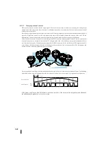
A powerful way to detect process failures early is to monitor the rate of change in PV. In most controls, the PV value changes
slowly. Factors that cause the PV value to change relatively quickly include disconnection of the signal line of the PV or control
output, and errors in the SP value. If the operator responds quickly and effectively to a PV change rate alarm, the absolute PV
value will not destroy the material in the process.
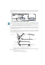
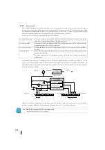
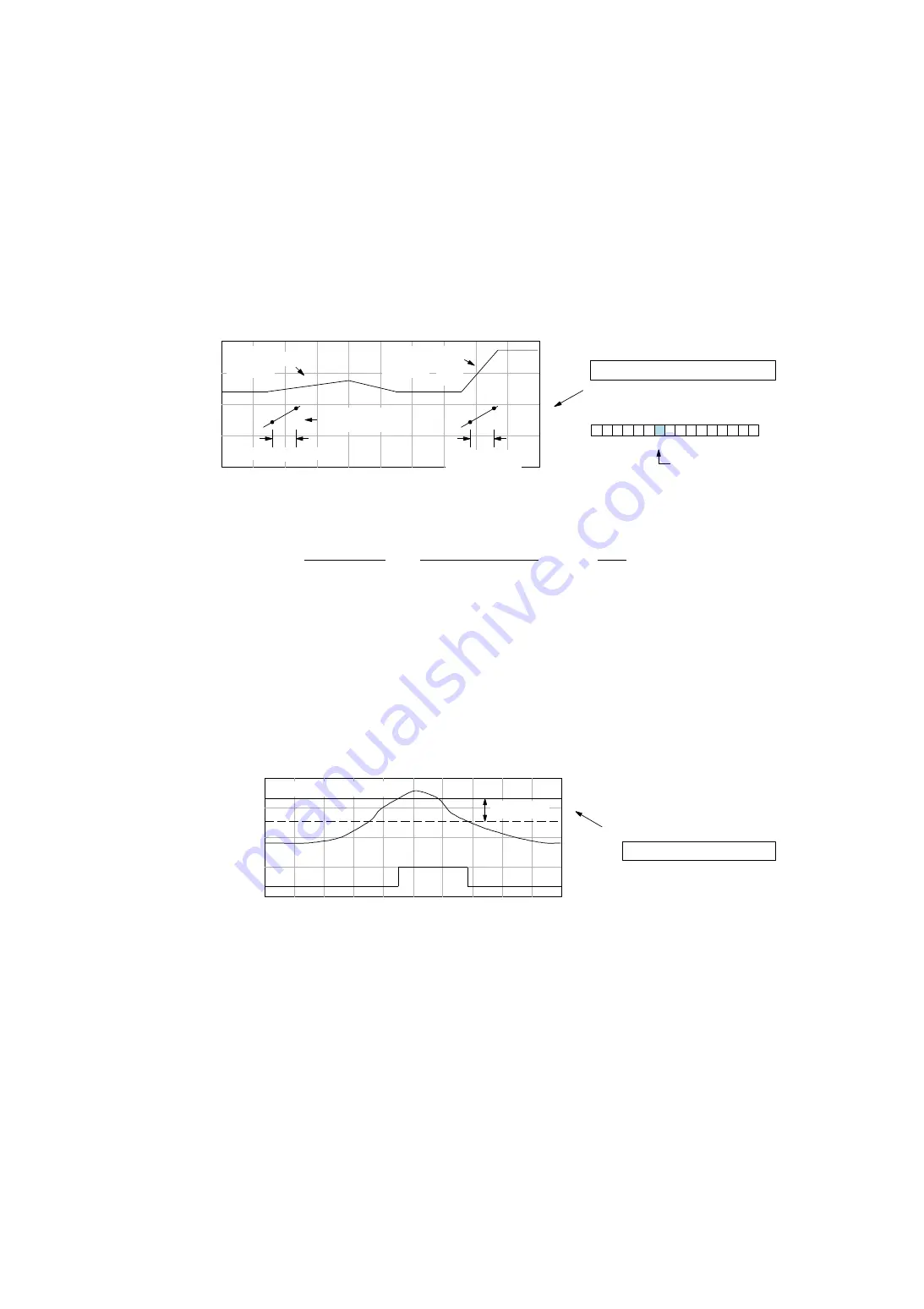
PID control can set the rate of change of PV as shown below. The rate of change specifies the change in PV per sample time for
PID control. This value is programmed into R+21 at the control table position.
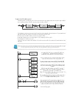
As an example, assume that the PV is the temperature for the process and give an alarm when the temperature changes more
than 15 degrees per minute. PV counts and PID control sample rates per degree are required. If the PV value (R+03) is 10
counts per degree and the loop sample rate is 2 seconds, use the following formula to convert the units of measurement into
counts/sample cycles:
The value "5" is programmed into the control table as the rate of change from the calculation results. The PV change rate alarm
can be set on/off independently of other PV alarms, using bit 14 of PID mode setting 1R+00.
The alarm hysteresis function (described below) does not affect the rate of change alarm.
5-12-7
PV alarm hysteresis
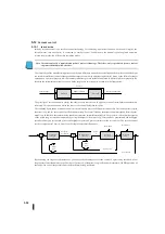
The PV absolute and PV deviation alarms are programmed using thresholds. When the absolute or deviation exceeds the
threshold, the alarm is activated. Actually, the PV signal may cause some noise or change in the PV value of the CPU. When the
PV value exceeds the alarm, the alarm is intermittent. This is resolved by using the PV alarm hysteresis function.
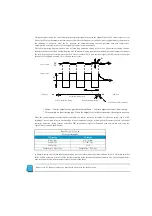
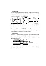
The PV alarm hysteresis can be set in the range of 1-4095 (BCD). When using the PV deviation alarm, the amount of hysteresis
must be set to less than the deviation. The following figure shows how hysteresis is applied when the PV value exceeds the
threshold and returns below the threshold.
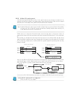
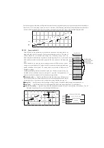
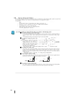
The hysteresis dose is applied only after the threshold is exceeded and then back to the safety zone. In this manner, the alarm is
activated immediately when the programmed threshold is exceeded. It also delays the release of the alarm until the PV value
falls below the threshold and the amount of hysteresis decreases.
R+21
XXXX
PV
0
1
3
4
5
6
7
8
9
10
11
12
13
14
15
2
Bit
PV
傾度:良好
PV
傾度:過度
サンプル時間
サンプル時間
変化率アラーム
ループテーブル
PV
変化率アラーム
PID
モードとアラーム状態ワード:
R
+
06
PV
変化率アラーム
ビット
=
X
=
=
アラーム変化率
150
1
分間
10
計数
/
度
30
ループサンプル
/
分
30
5
計数
/
サンプル周期
15
度
R+22
XXXX
PV
0
1
アラームのしきい値
ループテーブル
PV
アラームヒステリシス
ヒステリシス
アラーム
PV
gradient
OK
PV
gradient
Ex
ce
ssi
ve
Rate of change
alarm
Sample time
Sample time
PV rate of change alarm
PV rate of change alarm
PID mode and alarm state word
Bit
Loop table
Rate of change
of alarm
15 degree
1 minite
10 times calculation / degree
30 loop sample / minite
5 times calculation / sample cycle
Threshold value of the alarm
Hysteresis
Loop table
PV alarm hysteresis
Alarm
Summary of Contents for Kostac SJ-Ether Series
Page 1: ...English version of the KOSTAC SJ Ether series user s manual SJ ETHER USER M...
Page 12: ......
Page 13: ...1...
Page 14: ......
Page 88: ......
Page 89: ......
Page 113: ...3 24 Note Refer to 6 3 3 Module Assembly for connections and locks between modules...
Page 153: ......
Page 156: ...flashing OFF Not sent H W RX Green flashing Receiving H W OFF Not received H W...
Page 161: ...4 8...
Page 221: ......
Page 310: ...Chapter 7 Maintenance...
Page 311: ......

