5-56
5-12-8
Alarm program error
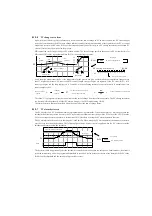
To enable the PV alarm threshold, a mathematical relationship must be established. The relationship is listed below. If this
relationship is not met, the alarm setting error bit shown on the right is set.
PV Absolute Alarm Condition: Low low < Low < High < High-high
PV deviation alarm condition: Yellow < Red
5-13
Lamp-soak generator
5-13-1
Introduction
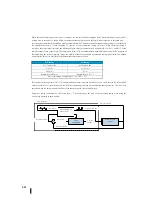
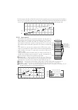
First, in the basic PID control operations, we have explained that PID control set points are generated in various ways by control
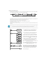
operating mode and programming. In the figure below, the lamp/soak generator is one way to create an SP. At any time, the SP
value must be set to R+02 with only one source considering safety.
If the SP value of the process is rarely changed or step changes are acceptable, no lamp/soak is needed to be used. However,
some processes require precise control of the SP value. The lamp/soak can significantly reduce the amount of programs needed
for these applications.
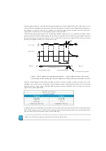
The terms "lamp" and "soak" have special meanings in the Process Control Industry Association and provide the required set
point (SP) values in the temperature control application. In the figure to the right, the SP value increases in the lamp section and
is maintained at a constant value in the soak section.
Complex SP settings can be created by specifying a set of lamp/soak data. The
lamp section is specified in seconds as the percentage change in SP. The soak
time is specified in minutes.
As shown below, you can see the lamp/soak generator as a special feature for
creating SP values. It has two input categories for generating SP values. The
lamp/soak operation defined lamp/soak table must be programmed first.
Control is read from this table during PID operation. Lamp/soak control is the bit of a special control table that controls the
function of the lamp/soak generator in real time. The status of the lamp/soak profile (current slope/segment number) can be
monitored from the ladder circuit.
Typical lamp/soak operation features are shown below.
Each PID control has a dedicated lamp/soak generator (optional).
You can specify up to eight lamps/soaks (16 sections).
When PLC is in RUN mode, you can run the lamp/soak generator at any time. The operation is independent of the control
mode (manual or automatic).
The lamp/soak can be controlled in real time, starting, holding, releasing, and JOG (to the next step).
The lamp/soak monitor contains the profile completion state, the soak deviation state (SP-PV), and the current lamp/soak step
number.
傾斜
ランプ
ソーク
時間
SP
+
–
セットポイントソース:
オペレータ入力
ランプ
/
ソークジェネレータ
ラダー回路
別のループの出力(カスケード)
セットポイント:
R
+
02
ループ演算
制御出力
プロセス変数
+
–
ランプ
/
ソークテーブル
セットポイント
プロセス変数
ループ演算
ランプ
/
ソークジェネレータ
ランプ
/
ソーク制御
制御出力
プロセス変数
Set point source :
Operator input
Lamp / Soak generator
Ladder circuit
Another loop output (cascade)
Loop
calculation
Set point
Control
output
Process variable
Lamp
Soak
Gradient
Time
Lamp / Soak table
Lamp / Soak generator
Lamp / Soak
control
Loop
calculation
Control
output
Process variable
Process variable
Set point
Summary of Contents for Kostac SJ-Ether Series
Page 1: ...English version of the KOSTAC SJ Ether series user s manual SJ ETHER USER M...
Page 12: ......
Page 13: ...1...
Page 14: ......
Page 88: ......
Page 89: ......
Page 113: ...3 24 Note Refer to 6 3 3 Module Assembly for connections and locks between modules...
Page 153: ......
Page 156: ...flashing OFF Not sent H W RX Green flashing Receiving H W OFF Not received H W...
Page 161: ...4 8...
Page 221: ......
Page 310: ...Chapter 7 Maintenance...
Page 311: ......

