5-14
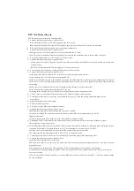
Troubleshooting tip
Q. PID control does not switch to automatic mode.
A. Examine the following points as a possible cause.
A PV alarm has occurred or a PV alarm program error has occurred.
PID control is the higher-level control of the cascaded pair, and lower-level control is not the cascade mode.
Q.
PID control is in automatic mode, but the control output remains zero.
A Examine the following points as a possible cause.
The upper limit of the control output stored in the control table R+31 is zero.
The PID control is saturated because the deviation is not zero and the (arithmetic) sign of the deviation is changed.
Q. The control output value is not zero but is not the correct value.
A Examine the following points as a possible cause.
Is the gain value correct? The gain is entered in the PID control table with the BCD value, but SP and PV are entered with
binary notation.
KPP can convert binaries to BCDs to display SP, PV, and control output.
Q. Even if the start bit is turned on, the lamp/soak generator will not operate.
A. Examine the following points as a possible cause.
Is the lamp/soak enable bit OFF? Bit 11 of R+00 in the control parameter table must be 1.
Is the retaining bit or other bit for lamp/soap operation ON?
Is the initial SP value the same as the initial SP value at the end of the lamp?The first lamp section is flattened and the retention
time is lost. As a result, the lamp/soak generator immediately moves into the soak section, giving the illusion that the first lamp is
not working.
Is the control set to cascade mode, and does it attempt to read SP values from the remote side?
Is the SP upper limit value in the control table R+27 too low?
Is writing to the SP value (R+02) performed?Start the lamp/soak generator manually to check.
Q. The PV value is set from the analog module, but the PV value in the table remains the same.
A. The analogue value is not written to the control table R+03 properly. Check that analog module and ladder circuit
are working.
Q. Differential gain does not affect output.
A. Enable the differential filter.
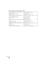
Q. The set point of the PID control changes arbitrarily.
A. Examine the following points as a possible cause.
The lamp/soak generator becomes enabled and a set point is created.
It may be switching PID control from manual to automatic mode. PID control automatically sets SP=PV
(Bumpless function)
It may be changing the SP value (R+02 in the control table) in the ladder circuit.
Q. Entering SP and PV values from KPP will function normally, but this data will be written from the ladder program.
These values do not function properly.
A. In the PID display of KPP, you can enter SP, PV, and bias values in decimal. In addition, it is displayed in decimal so that it can be
read easily. For example, if the data format is set to 12 bits and unipolar, the value range is 0 to 4095.
Since the value in the control table is hexadecimal, KPP automatically converts the value.
The values stored in the table range from 0 to FFF (12 bits, for unipolar format).
Q. Changing gains to different values does not stabilize PID control and makes adjustments impossible.
A. Examine the following points as a possible cause.
The PID control sample time is set too long.
The gain is too large. First, start with zero differential gain. If necessary, decrease integrate gain next. And lastly, decrease
proportional gain.
The major delay is in the process. This means that the PV responds slowly to the change in control output.
Is the distance between the actuator and the PV sensor too far apart? The ability of the actuator to give energy to the process
may be not enough.
There is a possibility that the disturbance exceeds the PID control capacity. Make sure that the PV is relatively stable when the
SP does not change.
Summary of Contents for Kostac SJ-Ether Series
Page 1: ...English version of the KOSTAC SJ Ether series user s manual SJ ETHER USER M...
Page 12: ......
Page 13: ...1...
Page 14: ......
Page 88: ......
Page 89: ......
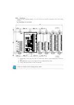
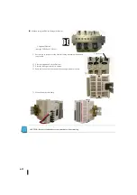
Page 113: ...3 24 Note Refer to 6 3 3 Module Assembly for connections and locks between modules...
Page 153: ......
Page 156: ...flashing OFF Not sent H W RX Green flashing Receiving H W OFF Not received H W...
Page 161: ...4 8...
Page 221: ......
Page 310: ...Chapter 7 Maintenance...
Page 311: ......

