6-10
6-3-2
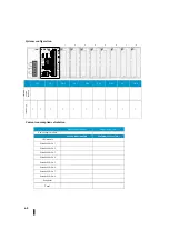
Module array setting
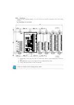
Since it is preferable to separate the AC and DC lines on the wiring for I/O, consider that the AC and DC lines are separated in
order to determine the module layout.
Checking items
・
Input/output
・
AC/DC
・
Resistance to noise (i.e., mounting the noise source device and the I/O wired away from the CPU)
・
Programmable I/O number
6-3-3
Module assembly
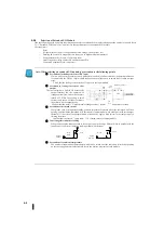
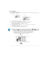
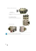
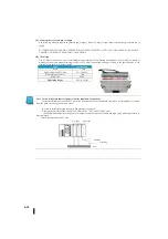
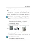
Based on the module arrangement, assemble the module fixing it with the connection module fixing mechanism.
The way to fix it is as follows.
①
Slide the lock lever of the connecting module fixing mechanism to the
UNLOCK and unlock the lock.
②
Hold the two connected modules in parallel and assemble the expansion
module connection terminals together with the irregularities of the
connection module fixing mechanism so that the gap does not open.
③
Slide the lock lever to the LOCK to secure the two module
connections.
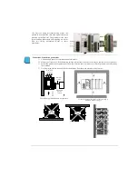
Note: Before assembling the CPU module and the extended I/O module, make sure that the power supply module is
turned off before connecting the module.
Do not insert or disconnect the module, such as a configuration change, while the power is turned on. The SJ Ether
series PLCs are not compatible with the module plugging and unplugging when the power is turned on. Be sure to turn
off the power supply and check that the PWR LED goes off before changing the module configuration.
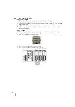
③
↑
①
②
←
←
Summary of Contents for Kostac SJ-Ether Series
Page 1: ...English version of the KOSTAC SJ Ether series user s manual SJ ETHER USER M...
Page 12: ......
Page 13: ...1...
Page 14: ......
Page 88: ......
Page 89: ......
Page 113: ...3 24 Note Refer to 6 3 3 Module Assembly for connections and locks between modules...
Page 153: ......
Page 156: ...flashing OFF Not sent H W RX Green flashing Receiving H W OFF Not received H W...
Page 161: ...4 8...
Page 221: ......
Page 310: ...Chapter 7 Maintenance...
Page 311: ......

