Chapter 2 Systems specification
2-7
2-3
I/O configuration
This section describes the basic configuration and arrangement.
(1)
Systems specification
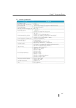
I t e m
Specification
Maximum number of modules installed
8 modules
Number of I/O points per module
4/8/16 points
Total number of I/O points (number of I/O points
to be implemented)
Up to 142 points
(including 14 CPU modules)
(2)
Slot No. (Slot No.)
The slot number is 0 for the CPU module, 1 for the extended I/O module next to the CPU module. The number of the
module increases from the left to the right.
(3)
How to assign I/O relay numbers
I/O embedded in the CPU is numbered as follows.
Inputs are I 00 to 07 (Analog type is 00 to 03)
Output: Q 00-05 (Analog type: 00-03)
I/O of the extension is assigned to I/Q100, I/Q200, I/Q300, and I/Q1000 in order of proximity to the CPU.
The four-point module occupies an area of eight points, and the vacant number can be used as an internal relay.
Example: Slot No. 0 1 2 3 4 5 6 7 8
P
o
w
er
b
as
e
Built-in CPU I/O
Eight
points
Input
Module
Eight
points
Input
Module
16 points
Input
Module
Four
points
Output
Module
Eight
points
Output
Module
Eight
points
Output
Module
Eight
points
Output
Module
Eight
points
Output
Module
I00
~
I07
Q00
~
Q05
I100
~
I107
I200
~
I207
I300
~
I317
Q400
~
Q407
Q500
~
Q507
Q600
~
Q607
Q700
~
Q707
Q1000
~
Q1007
R40400
Lower
R40500
Lower
R40404
R40410
R40414
R40520
R40524
R40530
R40540
R40544
Slot number
Input start number
(I)
Output start number
(Q)
0 (built-in CPU I/O)
I 0000 ~
Q 0000 ~
1
I 0100 ~
Q 0100 ~
2
I 0200 ~
Q 0200 ~
3
I 0300 ~
Q 0300 ~
4
I 0400 ~
Q 0400 ~
5
I 0500 ~
Q 0500 ~
6
I 0600 ~
Q 0600 ~
7
I 0700 ~
Q 0700 ~
8
I 1000 ~
Q 1000 ~
PWR
RUN
ERR
PORT3
LNK/ACT
ETHER
NET
100MBIT
PORT1
TX1
RX1
RS-232C
PORT2
RS-485
TX2
RX2
LG
ー
ー
ー
ー
+
+
+
+
TREM
RUN
C0
0
1
2
3
C1
0
1
2
3
AD1V
AD1I
AD2V
AD2I
ACOM
DA1V
DA1I
DA2V
DA2I
O
O
O
O
U
U
U
U
T
T
T
T
IIII
N
N
N
N
SJ-12DD1E-D
KO STA C
Koyo
+V
電源
CPU ( 0 )
1
2
3
4
5
6
7
8
Power supply
Summary of Contents for Kostac SJ-Ether Series
Page 1: ...English version of the KOSTAC SJ Ether series user s manual SJ ETHER USER M...
Page 12: ......
Page 13: ...1...
Page 14: ......
Page 88: ......
Page 89: ......
Page 113: ...3 24 Note Refer to 6 3 3 Module Assembly for connections and locks between modules...
Page 153: ......
Page 156: ...flashing OFF Not sent H W RX Green flashing Receiving H W OFF Not received H W...
Page 161: ...4 8...
Page 221: ......
Page 310: ...Chapter 7 Maintenance...
Page 311: ......

