Chapter 2 Systems specification
2-9
2-4
Function memory
Functional memory is a memory that stores the ON/OFF state and numeric data used in user programs. Functional memory
numbers (octal numbers) are separated by initial characters called identification symbols.
2-4-1
Function memory list
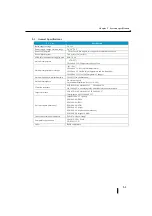
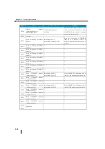
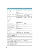
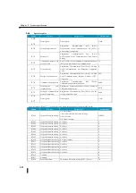
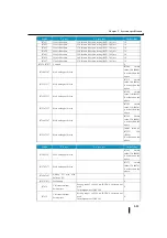
The following table lists the functional memories that can be used in SJ Ether series and their ranges.
Identi
ficatio
n
Symb
ol
N a m e
Bit number
Register number
Remarks
S co p e
Point
S c o p e
Number of
words
I
Input relay
I
~
0 1777
1024
points
~
R 40400 40477
64 W
Q
Output relay
Q
~
0 1777
1024
points
~
R 40500 40577
64 W
GI
Link input
GI
~
0 3777
2048
Point
~
R 40000 40177
128 W
GQ
Link outputs
GQ
~
0 3777
2048
Point
~
R 40200 40377
128 W
M
Internal relay
M
~
0 3777
2048
points
R 406
~
00 40777
128 W
S
Stage
S
~
0 1777
1024
points
~
R 41000 41077
64 W
T
Timer
T
~
0 377
256
points
~
R 41100 41117
32 W
C
Counter
C
~
0 377
256
points
~
R 41140 41547
32 W
SP
Special relay
SP
~
0 777
512
points
~
R 41200 41237
16 W
Relay defined in the
system
R
Timer
Elapsed value
-
-
~
R 00000 00377
256 W
Per timer point
1 word (4 digits)
Counter
Elapsed value
-
-
~
R 01000 01377
256 W
Per counter
1 word (4 digits)
Data
Register
-
-
~
R 00400 00777
12960 W
-
-
~
R 01400 07377
-
-
~
R 10000 27777
Special register
-
-
~
R 07400 07777
256 W
PLC system reservation
Note :
1:
2:
3:
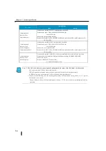
One register [word] is 2 bytes [16 bits (point)].
There is a spare area in the special relay or special register area that does not specify the application. However,
since this area is defined by the system side, do not write data by user programs, etc.
The commands that use BCD8 digits, such as the accumulated value timer (ATMR) or addition/subtraction
counter (UDCNT), use two words of the elapsed value register. (Be careful of duplicate use)
Summary of Contents for Kostac SJ-Ether Series
Page 1: ...English version of the KOSTAC SJ Ether series user s manual SJ ETHER USER M...
Page 12: ......
Page 13: ...1...
Page 14: ......
Page 88: ......
Page 89: ......
Page 113: ...3 24 Note Refer to 6 3 3 Module Assembly for connections and locks between modules...
Page 153: ......
Page 156: ...flashing OFF Not sent H W RX Green flashing Receiving H W OFF Not received H W...
Page 161: ...4 8...
Page 221: ......
Page 310: ...Chapter 7 Maintenance...
Page 311: ......

