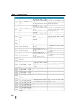
Chapter 2 Systems specification
2-11
(3)
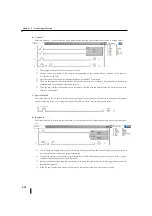
Internal relay M
Functional memory M is a status memory for storing the execution results of user programs and using them for internal
processing.
①
Relay (auxiliary relay) used only for logical operations inside the CPU.
②
There is no limit on the number of relay M used on user programs as a condition such as A contact and B contact.
③
When the power failure hold setting is used, the on/off status of the internal relay can be stored even in the event of
a power failure.
(4)
Stage S
Functional memory S is a status memory that stores the operation status of a stage representing a process in a staged
program.
①
Specify the function memory number for the process number in the SG and ISG commands.
②
Specify the destination of the transition process in the JMP and NJMP commands.
③
The stage can be forcibly turned on/off with the SET and RST commands.
④
Stages can be used as contact conditions such as LD commands. There is no limit to the number of contacts used.
⑤
When the power failure hold setting is used, the stage ON/OFF state can be stored even in the case of a power failure.
(5)
Timer T
Functional memory T is a status memory in which the timer operates and the set time has passed (time-up status).
①
The execution result of the timer is stored.
②
The elapsed time of the timer is stored in a register (elapsed value register) corresponding to the timer number.
、
(T0=R0 T1=R1)
③
The RSTTC command resets the time-up status and elapsed values.
④
There are four types of timer commands: a 0.1 second/0.01 second incremental timer and a 0.1 second/0.01 second
summation timer.
⑤
When the power failure hold setting is used, the timer ON/OFF state and elapsed value can be stored even in the
event of a power failure.
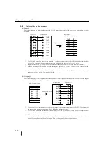
STAGE
Mnemonic
Ladder
Mnemonic
0.1 sec incremental timer
Summary of Contents for Kostac SJ-Ether Series
Page 1: ...English version of the KOSTAC SJ Ether series user s manual SJ ETHER USER M...
Page 12: ......
Page 13: ...1...
Page 14: ......
Page 88: ......
Page 89: ......
Page 113: ...3 24 Note Refer to 6 3 3 Module Assembly for connections and locks between modules...
Page 153: ......
Page 156: ...flashing OFF Not sent H W RX Green flashing Receiving H W OFF Not received H W...
Page 161: ...4 8...
Page 221: ......
Page 310: ...Chapter 7 Maintenance...
Page 311: ......


