・
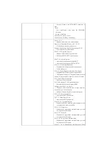
Port specification when MWX/MRX instruction is
used
Port3
・
Port specification when using the EWX/ERX
command
Method of Addition
Overall review (please: Go to)
⇒
Overall review (watchdog watchdog)
For P.1-2-1-2
・
Addition of function list by model number
Properties of Functional Memory in P.2-12 2-4-2
・
(11) Modify pointer P description text
Functions/Performance/Specifications on page 28-2-2
・
Correct the number of commands
P.39-43-2-4-3 Special Relay List
・
Addition of SP112,SP113 specifications
・
Addition of SP254-SP777 specifications
P.40-47 2-4-4 special register
・
Addition of specifications for R400-R777
・
Addition of specifications of R7702-R7705
P.52-5-3 List of System Parameters
・
Programmable, Ethernet port description added
・
To add backup text
P53 2-5-4 System Parameter Individual Description
・
Programmable, Ethernet port description added
・
"Hold power failure area" The power failure retention
time due to a large capacity capacitor is 4 hours. Deleted.
P56 2-7 Self-Diagnostic Function
・
E099 causes were corrected.
P61 2-8-Switching of 3 CPU operation modes
・
Replace with the screen diagram of KPP.
Setting without P63 2-10-2 battery
・
The power failure retention time of large capacitors
was deleted by 4-hour description.
・
Addition of caution for power failure holding area
P53 2-13-2 List of Components
・
Addition of STEP2 part number
P83 3-1-1 Model Number List
・
Addition of STEP2 part number
P.144-145 4-1-1 programmer port
・
Explanation of fixed serial and general-purpose serial
communication modes was added.
P.151 4-2-1 K Sequences
・
Explanation of programmer communication port and
description of each register
P.153 4-2-2 DirectNET
・
Explanation of programmer communication port and
description of each register
P.163 4-2-8 No-procedure communication
・
Explanation of programmer communication port and
description of each register
P.168-171 4-2-13 Transmission and Reception Mode
Summary of Contents for Kostac SJ-Ether Series
Page 1: ...English version of the KOSTAC SJ Ether series user s manual SJ ETHER USER M...
Page 12: ......
Page 13: ...1...
Page 14: ......
Page 88: ......
Page 89: ......
Page 113: ...3 24 Note Refer to 6 3 3 Module Assembly for connections and locks between modules...
Page 153: ......
Page 156: ...flashing OFF Not sent H W RX Green flashing Receiving H W OFF Not received H W...
Page 161: ...4 8...
Page 221: ......
Page 310: ...Chapter 7 Maintenance...
Page 311: ......


