3-4
(2)
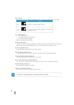
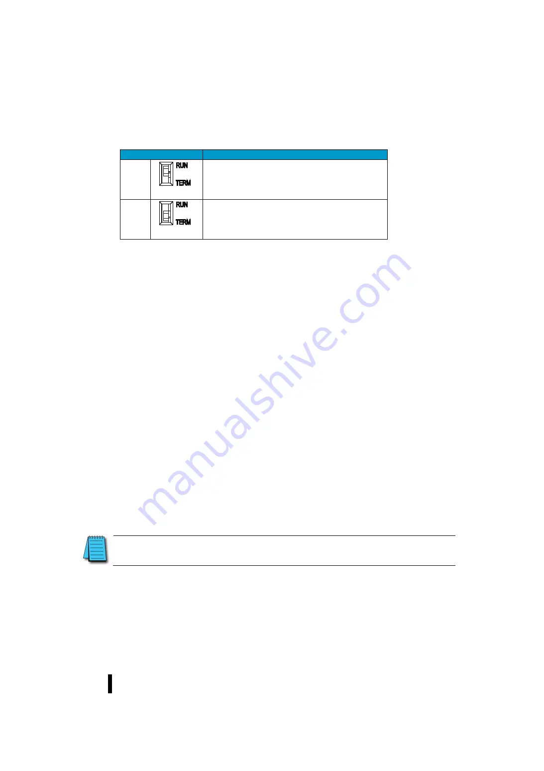
Mode-switch
This is the slide switch for selecting the operation mode of the PLC. This is the two positions of the RUN and TERM.
M o d e
Description
RUN
The CPU is in operation (forced RUN mode).
TERM
Operation of mode change (RUN/TEST/STOP) can be performed
by peripheral devices.
(3)
Communications port
①
Port 1 (programmer port)
②
Port 2 (general purpose communication port)
③
Port 3 (EtherNet communication port)
Refer to 4-1 Communication port for details.
(4)
Battery holder (upper)
For SJ Ether series high-performance and analogue types, a lithium battery (commercially available CR2354) can be used to
retain the content of the system RAM storage memory even if it is not connected to an external power source.
(5)
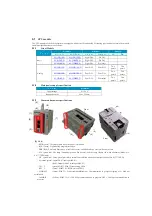
I/O terminal block connector
A removable European terminal block connector with I/O terminals.
(6)
Power input terminal block (lower)
A removable European-type terminal block with DC 24 V from power modules and frame ground terminals.
(7)
Extended module connection terminal (side)
When installing an extended I/O, disconnect the cover and connect it.
(8)
Connection module fixing mechanism (upper/lower)
This is a mechanism to secure the connection when connecting to the power module or installing an extended I/O.
(9)
DIN rail fixing mechanism (rear)
This is a mechanism for securing to the DIN rail.
(10)
Screw hole for fixing module (back)
If the DIN rail is not used, secure the module directly with a screw.
Note: Refer to 6-3-3 Module Assembly for connections and locks between modules.
Summary of Contents for Kostac SJ-Ether Series
Page 1: ...English version of the KOSTAC SJ Ether series user s manual SJ ETHER USER M...
Page 12: ......
Page 13: ...1...
Page 14: ......
Page 88: ......
Page 89: ......
Page 113: ...3 24 Note Refer to 6 3 3 Module Assembly for connections and locks between modules...
Page 153: ......
Page 156: ...flashing OFF Not sent H W RX Green flashing Receiving H W OFF Not received H W...
Page 161: ...4 8...
Page 221: ......
Page 310: ...Chapter 7 Maintenance...
Page 311: ......


