3
Koyo Digital Timers
www
.aut
oma
tiondir
ect.com
2
3
5
DC
output
1
7
Reset Input
8
9 10 11 12
KT-V4S
0V
COM N.C. N.O.
KT-V4S-C
1
3
5
7
Reset Input
8
9 10 11 12
0V
COM N.C. N.O.
+
Power In
Power In
24VDC, 60mA
Sensor supply
Start
Input
Start
Input
DC
output
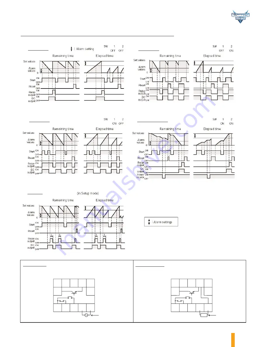
Koyo Digital Timers Timing and Wiring Diagrams
Note: Output duration is variable from 0-9990 ms. (Default: 100 ms)
When alarm settings are 0, the DC
output is the same as the output
operations for a relay output.
Note: Alarm settings should be less than preset values. Using
alarm settings with values that exceed preset values will result
in measurement values of 0 and the alarm output (DC output)
will come ON.
On-delay
Off-delay
One-shot
Accumulation
Flicker
KT-V4S-D
KT-V4S-C-D
Summary of Contents for KT-V4S-C-D
Page 4: ...w w w a u t o m a t i o n d i r e c t c o m 4 Koyo Digital Timers lI O Circuit Diagrams...
Page 6: ...w w w a u t o m a t i o n d i r e c t c o m 6 Koyo Digital Timers...
Page 7: ...7 Koyo Digital Timers w w w a u t o m a t i o n d i r e c t c o m...
Page 8: ...w w w a u t o m a t i o n d i r e c t c o m 8 Koyo Digital Timers...
Page 9: ...9 Koyo Digital Timers w w w a u t o m a t i o n d i r e c t c o m...
Page 10: ...w w w a u t o m a t i o n d i r e c t c o m 10 Koyo Digital Timers...


