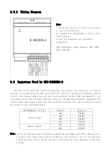
The option function board does not occupy the normal I / O points.
The following describes The registers used by the analog input / output of this option
function board are described as follow.
2.6.1 Analog Input Registers
This optional function board has 4 analog input channels. Each channel has its
designated R register to store the digital conversion data (HEX) of the analog voltage
value from the corresponding input terminal. The input registers corresponding to its
input channels: AD1 – R37420, AD2 – R37421, AD3 – R37422, and AD4 – R37423. The
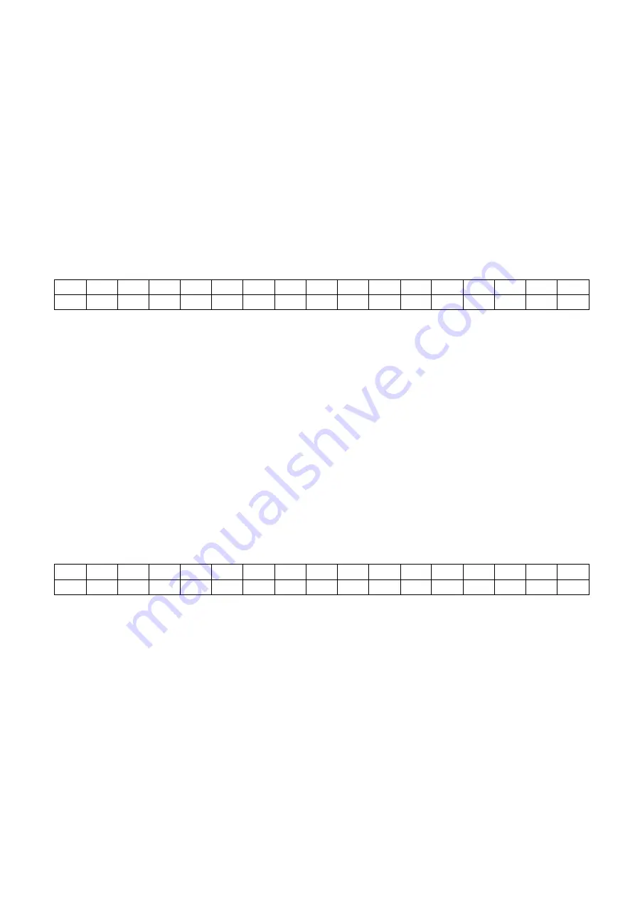
format of the conversion data is as follows:
Bit
15
14
13
12
11
10
9
8
7
6
5
4
3
2
1
0
0
0
0
0
*
*
*
*
*
*
*
*
*
*
*
*
The range of conversion data is 0 ~ 0x0FFF.
Note: Please do not apply voltage signals other than 0-10V to the input terminal
of this function board, otherwise the option function board and NK1 series PLC main
unit may be damaged.
2.6.2 Analog Output Registers
This option function board has 2 analog output channels, and each analog output
channel has its designated R register for setting the analog value (HEX) . When a value
is set in this register, this function board automatically outputs a 0-10V voltage signal
corresponding to the set value at the corresponding analog output terminal.
The setting registers corresponding to the output channels: DA1 – R37424 and DA2
- R37425. The format of its analog output setting data is as follows:
bit
15
14
13
12
11
10
9
8
7
6
5
4
3
2
1
0
*
*
*
*
*
*
*
*
*
*
*
*
Note: The valid setting range of the output analog data is 0 ~ 0xFFF; if the setting
data is greater than 0xFFF, the system automatically intercepts the valid part of
the setting value.


