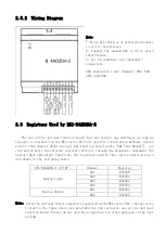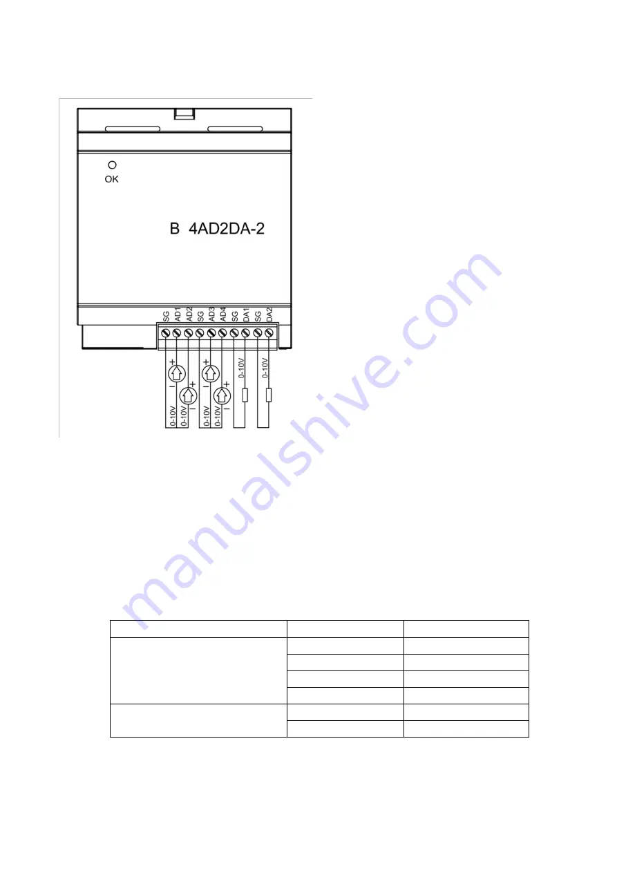
2.5.2 Wiring Diagram
Note:
1、Do not mix the wires of different channels
to avoid interference.
2、Connect the unused ADn to SG to avoid
interference.
3、All SG terminals are internally
connected.
ADn represents input channels AD1,AD2,
AD3,and AD4.
2.6 Registers Used by NK1-B4AD2DA-2
The use of the optional function board does not require any settings, as long as
the unit is installed on the NK1 series PLC (for specific installation methods, please
refer to the chapter about the optional function board in the "NK1 User Manual"), you
can read or write the relevant registers directly through the program to implement the
analog input and output functions. The registers used by this option function board
are shown in the following table.
NK1-B4AD2DA-2(0-10V)
Channel
Register
Analog Input
AD1
R37420
AD2
R37421
AD3
R37422
AD4
R37423
Analog Output
DA1
R37424
DA2
R37425
Note: After the optional function board is installed on the NK1 series PLC, the registers
listed in the table above are provided for the exclusive use of the optional
function board. Please do not use these registers for other purposes in the user
system.


