Page 8
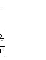
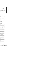
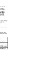
Table 1. Clearance Dimensions
Additional installation information can be found in the “Typical Installation Configura-
tions” section and your venting manufacturer/supplier’s literature.
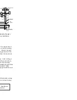
INSTALLATION COMMENT: We recommend sufficient space be
provided (minimum 20 inches/500 mm) on each side of the heater to service
the equipment area. If this is not possible, a provision must be made to pull
the heater out for service.
Dimension
Description
Previa
A
Unit to s ide w all or side
f ac ing
5" (125 mm)
B
Unit to back w all
1 " (25 mm)
C
Corner of unit to w all
1 " (25 mm)
D
A lcov e height
48 " (1220 mm)
E
Overall unit height
30 " (760 mm)
F
A lc ov e depth (Maximum)
30 " (760 mm)
G
A lc ove w idth
34" (865 mm)
H
Floor to centerline air intake
5.125 " (130 mm)
I
Floor to centerline exhaus t
14.5" (370 mm)
J
Unit to mantle
N/A
K
Unit to top f acing
N/A
A ll dimensions are minimum dimensions unless marked.
Summary of Contents for MX2
Page 2: ...EFTBLANK ...
Page 3: ...Page 3 s se td at 07 ...
Page 7: ...Page 7 lease note that turer supplier has or C BACKWALL ...
Page 9: ...Page 9 ced 0 mm in uilding or eater A r heater ion on the manual ...
Page 25: ...Page 25 d one near ugs in one to and ing irculation fan ated in the This will oved ash es ...
Page 31: ...Page 31 maker or your t resolve your ...
Page 33: ...Page 33 6 ...
Page 34: ......
Page 35: ...Page 35 16 19 24 ...
Page 38: ......
Page 39: ...Page 39 ...
Page 40: ...M ...


