RUN THE GAS LINE
(continued)
1.
Run the gas line. An accessible shut off valve must be installed up stream from the regulator.
NOTE:
Do not run the incoming gas line in a manner that would obstruct the operation of the fan.
2 .
This fireplace is designed to accept either a 3/8" or 1/2" gas line approved for gas appliances. Consult local
building codes to properly size the gas supply line leading to a 3/8" reduction.
3.
A gas line access hole is located on either side of the fireplace for gas line connection.
4.
Connect the gas line to the manual shut-off valve.
5.
Connect the flexible gas line (installed on the millivolt board valve) to the manual shut off valve.
IMPORTANT!
ALL CONNECTIONS, WHETHER FIELD OR FACTORY MADE MUST BE CHECKED FOR LEAKS!
NOTE: The appliance and its individual shutoff valve must be disconnected from the gas supply piping sys-
tem during any pressure testing of that system at test pressures in excess of ½ psi.
NOTE: The appliance must be isolated from the gas supply piping system by closing its individual manual
shutoff valve during any pressure testing of the gas supply piping system at test pressures equal to or less
than ½ psi.
Pressure check taps for both the manifold (outgoing) & inlet (incoming) pressures are located in front of the
gas valve. The left pressure tap is the manifold pressure and the right pressure tap is the incoming pres-
sure. Follow instructions on page #23 for checking these pressures.
F)
SECURE THE MILLIVOLT BOARD. See Figures 12A - 12D.
NOTE: The fireplace is equipped with the millivolt board & burner/cover assembly already installed. Ensure
that all of the nuts are tightened, securing the board to firebox and the burner cover is properly secured. Fol-
low these procedures in the event this assembly needs to be removed for service and/or maintenance.
1. Turn the control knob to “OFF”.
2. Remove the upper grill, glass assembly, log &
burning embers.
3. Shut off the gas supply at the manual shut-off
valve.
4. Disconnect gas line flex tube from the manual
shut-off valve.
5. Disconnect any wall switch, remote control or
thermostat wires from the valve.
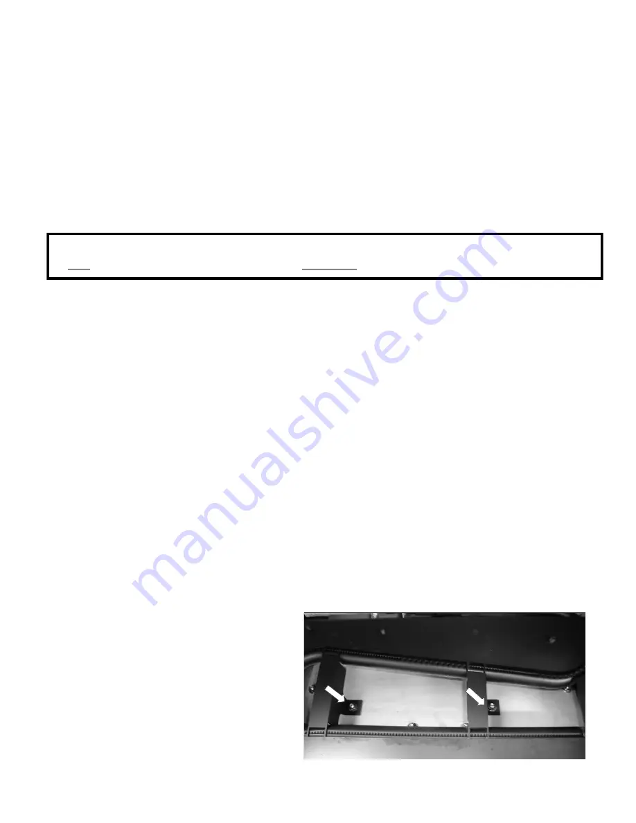
6. Loosen and remove the (2) nuts securing the
burner cover, Figure 12A.
7. Remove the burner cover and set aside.
Millivolt Board Removal
(if necessary)
¼” nuts securing burner cover
Figure 12A
8. Loosen and remove the (8) 1/4" nuts (the 8
along the edges only) securing the millivolt
board and, while grasping the board, gently lift
it off the (8) bolts and remove from the firebox.
Page 17


