background image

32


#LXL-22-L


R.1  4 . 2 0 . 2022


HUSSONG MFG. CO., INC.


KOZY HEAT FIREPLACES


WARNING: 

If you do not follow these instructions exactly, a fire or explosion may result causing property damage, personal injury, or loss of life.


9.0  OPERATING INSTRUCTIONS


SECTION 9 

OPERATING INSTRUCTIONS


FOR YOUR SAFETY READ BEFORE OPERATING


A.


This appliance is equipped with an ignition device which 
automatically lights the pilot. Do not try to light the pilot by 

hand.


B.


BEFORE OPERATING 

smell around the appliance area for gas. 

Be sure to smell next to the floor because some gas is heavier 

than air and will settle on the floor.


WHAT TO DO IF YOU SMELL GAS


Do not try to light any appliance.


Do not touch any electric switch; do not use any phone in 

your building.


Immediately call your gas supplier from a neighbor’s phone.


WARNING


Do not operate appliance with the glass front removed, cracked, or 

broken. Replacement of the glass should be done by a licensed or 

qualified service person.


Under no circumstances should any solid fuel (wood, coal, paper, 

cardboard, etc.) be used in this appliance.


Children and adults should be alerted to the hazards of high surface 

temperature and should stay away to avoid burns or clothing ignition.


Follow the gas supplier’s instructions.


If you cannot reach your gas supplier, call the fire 

department.


C.


Use only your hand to turn the gas control manual valve. Never 

use tools. If the valve will not turn by hand, do not try to repair 

it; call a qualified service technician. Force or attempted repair 

may result in a fire or explosion.


D.


Do not use this appliance if any part has been under water. 

Immediately call a qualified service technician to inspect the 

appliance and to replace any part of the control system and 
any gas control that has been under water.


CAUTION


Clothing or other flammable material should not be placed on or near 

the appliance.


Young children should be carefully supervised when they are in the 

same room as the appliance. Toddlers, young children and others 

may be susceptible to accidental contact burns. A physical barrier is 

recommended if there are at risk individuals in the house. To restrict 

access to a fireplace or stove, install an adjustable safety gate to keep 

toddlers, young children and other at risk individuals out of the room 

and away from hot surfaces.


OPERATING INSTRUCTIONS


1.


STOP! Read all the safety information above on this page.


2.


Press the wireless remote POWER button.


3.


Turn off all electric power to the appliance.


4.


This appliance is equipped with an ignition device which 

automatically lights the pilot. Do not try to light the pilot by 
hand.


5.


Locate the manual valve installed by your qualified service 
technician.


6.


Turn the manual valve clockwise   to the OFF position.


7.


Wait  five  (5)  minutes  to  clear  out  any  gas.  Then,  smell 

for gas, including near the floor. If you smell gas, STOP! 

Follow ‘B’ in the safety information above. If you do not smell 
gas, go to the next step.


8.


Turn the manual valve counterclockwise   to the ON position.


9.


Turn on all electric power to the appliance.


10.


Press the wireless remote POWER button.


11.


If the appliance will not operate, follow the instructions, “To 

Turn Off Gas To Appliance” and call your service technician or 

gas supplier.


OFF


ON


1.


Press the wireless remote POWER button.


TO TURN OFF GAS TO APPLIANCE


3. 

Locate  the  manual  valve  installed  by  your  qualified  service


2.


Turn off all electric power to the appliance if service is to be 

performed.


technician.


4. 

Turn the manual valve clockwise 

to OFF position.


NOTE


When this fireplace is initially lit, condensation will appear on the glass. This is normal in all gas fireplaces and will disappear after several 

minutes. A paint smell will occur during the first few hours of burning. It is recommended to leave the fan off during this period to help speed 

the paint curing process.


This fireplace may produce noises of varying degree as it heats and cools due to metal expansion and contraction. This is normal, and does not 

affect the performance or longevity of the fireplace.


POWER 

ON/OFF 

Summary of Contents for LAKEFIELD-2 2-L

Page 1: ...gency or the gas supplier WARNING FIRE OR EXPLOSION HAZARD Failure to follow safety warnings exactly could result in serious injury death or property damage English and French installation manuals are available through your local dealer Visit our website www kozyheat com Les manuels d installation en français et en anglais sont disponibles chez votre détaillant local Visitez www kozyheat com HOT G...

Page 2: ......

Page 3: ...he same for over 40 years We offer a complete line of gas wood and electric fireplaces along with stylish accessories to complement any decor Adding a fireplace is one of the best ways to increase the value of your home and we are proud to offer a network of dealers throughout the country to help make your experience everything you imagine We pride ourselves in being dedicated not only to function...

Page 4: ......

Page 5: ...1 6 1 Approved Vent Systems 21 6 2 Venting Requirements 21 6 4 Vent Installation 23 6 5 Class A Chimney Masonry Chimney Conversion 26 6 6 Coaxial to Co Linear Chimney Conversion 27 7 0 FIREPLACE SETUP 28 7 1 Safety Barrier Screen and Overlay Installation 28 7 3 LX22 500 Log Set Installation 29 7 4 Control Board Removal and Installation 30 8 0 ELECTRICAL INFORMATION 31 8 1 Electrical Specifications...

Page 6: ......

Page 7: ...ed however that during said thirty 30 day period a battery operated carbon monoxide detector with an alarm shall be installed 1 3 2 Approved Carbon Monoxide Detectors Each carbon monoxide detector as required in accordance with the above provisions shall comply with NFPA 720 and be ANSI UL 2034 listed and IAS certified A metal or plastic identification plate shall be permanently mounted to the ext...

Page 8: ...sdiction in you area regarding derate guidelines 2 1 1 1 US Installations Refer to the American Gas Association guidelines for the gas designed appliances derating method For elevations above 2 000 610m input ratings are to be reduced by 4 for each 1 000 305m above sea level 2 1 1 2 Canadian Installations When the appliance is installed at elevations above 4 500 1 372m the certified high altitude ...

Page 9: ... LXL 22 L R 1 4 20 2022 9 HUSSONG MFG CO INC KOZY HEAT FIREPLACES 2 3 Appliance Dimensions SECTION2 SPECIFICATIONS ApplianceDimensions FIGURE 2 1 LXL 22 L Dimensions ...

Page 10: ...nce and shall be installed for the protection of children and other at risk individuals If the barrier becomes damaged the barrier shall be replaced with Hussong Mfg Co Inc s barriers for this appliance Refer to section 7 1 SAFETY BARRIER SCREEN AND OVERLAY INSTALLATION on page 28 for installation instructions SECTION2 SPECIFICATIONS Safety BarrierScreenandOverlays FIGURE 2 2 Safety Barrier and Ov...

Page 11: ...G Due to high temperatures the appliance should be located out of traffic and away from furniture and draperies This gas stove must be installed on a level surface capable of supporting the gas stove and venting Determine your vent requirements before framing your appliance This appliance may be installed in a bedroom Please be aware of the large amount of heat this gas stove will produce when det...

Page 12: ...s T ab le 3 1 M in im u m A p p lian ce C learan ce s to C o m b u stib le M aterial From appliance top to sidewall 3 76mm From appliance top to back wall 3 76mm From appliance top corner to wall 1 1 2 38mm Floor to ceiling 68 1 4 1734mm From appliance top to ceiling 36 1 4 920mm From top of horizontal pipe surface to ceiling 2 1 4 57mm 14 7 16 443mm 1 38mm 14 3 8 365mm 3 76mm 3 76mm 1 38mm 14 7 1...

Page 13: ...n instructions for vertical terminations Attic insulation shields may be insulated using unfaced insulation products listed as non combustible per ASTM E 136 3 3 3 Horizontal Terminations IMPORTANT Horizontal vent sections require 1 4 6mm rise for every 12 305mm of travel Wall thimble products that comply with the required 1 25mm clearances to combustibles must be installed for all horizontal vent...

Page 14: ... 62 5 8 1591mm 52 1321mm 72 1829mm FIGURE 3 4 Alcove Front Wall Framing Alcove Installation 3 4 Alcove Installation Shown in FIGURE 3 3 is a top down view of a traditional alcove installation The alcove installation may have a front wall as shown in FIGURE 3 4 to visually hide the vent pipe and vent elbow as long as required clearances are met Minimum clearances MUST be maintained in order to prov...

Page 15: ...on where the gas stove sits inside of a masonry fireplace As referenced in FIGURE 3 5 the 3 4 19mm mantel trim can start at 40 1 2 1029mm above the floor with a 6 152mm mantel starting at 44 1118mm above the floor As referenced in FIGURE 3 5 clearances to combustibles sided in the front such as a mantel leg or a sidewall is 3 76mm from the masonry fireplace opening with an unlimited projection The...

Page 16: ...ollowing FIGURE 3 6 below The continuous insulated building envelope and weatherproof membrane are not to be interrupted by gas stove installation See FIGURE 3 7 on page 17 Gas stove operation is approved from 40 F to 110 F All wiring connections shall be in accordance with outdoor requirements of NECA NFPA 70 All clearances and requirements in your appliance manual must be adhered to A B C C The ...

Page 17: ... Continuous insulated building envelope and weatherproof membrane are not to be interrupted by gas stove installation Minimum weatherproof overhang in front and sides OUTSIDE INSIDE Free standing structure weatherproof enclosure FIGURE 3 7 Outdoor Covered Installation Guide 2 Minimum weatherproof overhang in front and sides ...

Page 18: ...sures equal to or less than psi 3 5 kPa the appliance must be isolated from the gas supply piping system by closing its individual manual shut off valve A listed and Commonwealth of Massachusetts approved 1 2 13mm tee handle manual shut off valve and flexible gas connector are to be connected to the 1 2 13 mm control valve inlet If substituting for these components please consult local codes for c...

Page 19: ...ctedtoa chimneyflue serving a separate solid fuel burning appliance Refer to FIGURE 5 1 below for vertical vent termination clearances SECTION5 TERMINATION LOCATIONS Minimum height H from roof Roof Pitch Feet Meters Flat to 6 12 1 0 0 30 Over 6 12 to 7 12 1 25 0 38 Over 7 12 to 8 12 1 5 0 46 Over 8 12 to 9 12 2 0 0 61 Over 9 12 to 10 12 2 5 0 76 Over 10 12 to 11 12 3 25 0 99 Over 11 12 to 12 12 4 ...

Page 20: ...ion air inlet to any other appliance 12 30cm 9 23cm K Clearance to mechanical air supply inlet 6 1 83m 3 91cm above if within 10 3m horizontally Massachusetts 10 3m L Clearance above paved sidewalk or paved driveway located on public property 7 2 13m M Clearance under veranda porch deck or balcony 12 30cm 12 30cm N Clearance between two horizontal terminations 12 30cm 12 30cm O Clearance between t...

Page 21: ... in this manual 6 1 1 Approved 4 x 6 5 8 Vent Systems NOTE Consult the local and national installation codes to assure adequate combustion and ventilation air is available Venting requirements apply to both natural gas and propane Flame height and appearance will vary depending upon venting configuration and the type of fuel used Provide a means for visually checking the vent connection to the app...

Page 22: ...t amount of restriction Follow FIGURE 7 1 for restrictor plate installation before attaching venting or through the baffle if venting is already attached This gas stove is shipped with the baffle restrictor set in position 1 wide open Position 1 is the least restriction and position 5 is the most restriction To adjust the baffle restrictor 1 Remove the safety barrier and glass frame assembly 2 Rem...

Page 23: ...nt Installation 6 4 1 Vertical Terminations Natural Gas and Propane Installations i Minimum Maximum Vertical Terminations 36 914mm minimum vertical length 50 15 24m maximum vertical length termination cap DIAG 1 NATURAL GAS PROPANE VERTICAL TERMINATIONS A 90 Elbow not applicable B Termination Cap B B 50 15 24m 36 914mm ...

Page 24: ...Minimum 36 Vertical Vent Pipe Minimum Horizontal 36 914mm vertical vent pipe 90 horizontal elbow termination cap Horizontal Terminations Natural ii Minimum 36 Vertical Vent Pipe Maximum Horizontal 36 914mm vertical vent pipe 90 horizontal elbow 8 2 44m maximum horizontal run termination cap iii Minimum 48 Vertical Vent Pipe Minimum Horizontal 48 1219mm vertical vent pipe 90 horizontal elbow termin...

Page 25: ...ust be within the shaded area in FIGURE 6 3 25 7 6m maximum vertical rise 25 7 6m maximum horizontal run 50 15 2m of total length CombinationVentingNatural Maximum of 5 90 elbows For each additional 90 elbow used after the first elbow 3 914mm must be subtracted from maximum venting allowed 2 45 degree elbows may be used in place of 1 90 elbow For each 45 elbow used 18 457mm must be subtracted from...

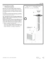
Page 26: ...ow DIAG 3 for allowable venting configurations for installation in existing through the ceiling Class A Masonry chimney Route the exhaust gases and intake air through the existing Class A Masonry chimney 6 5 1 4 Flex Pipe Venting Configurations IMPORTANT Horizontal vent sections require at least 1 4 6mm rise for every 12 305mm of travel IMPORTANT The vent heat shield assembly must be installed whe...

Page 27: ...e existing masonry chimney 6 6 1 Coaxial to Co Linear Venting Configurations IMPORTANT Horizontal vent sections require at least 1 4 6mm rise for every 12 305mm of travel IMPORTANT Careshouldbetakenwheninstalling flexiblepipeto avoid a tight bend that may cause abrasion or damage to the flexible pipe The vent option listed below allows for a minimum of 0 0mm to a maximum of 24 610mm horizontal run...

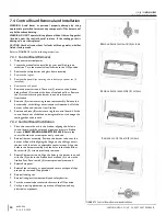
Page 28: ...ower into position To remove safety barrier screen lift the screen up and out of slots SECTION7 FIREPLACE SETUP SafetyBarrier ScreenandOverlayInstallation GlassFrameAssembly 7 2 Glass Frame Assembly WARNING Do not operate this fireplace with the glass removed cracked or broken Replacement of the glass assembly should be done by a licensed or qualified service person Refer to FIGURE 7 2 with the fo...

Page 29: ...e log LX2 in to position as shown in FIGURE 7 3 3 Align log LX3 with the notch in the ash panel and place into position as shown in FIGURE 7 3 SECTION7 FIREPLACE SETUP LX22 500LogSetInstallation LX22 500LogSetInstallation 4 Align the holes in the bottom of log LX4 with the studs on the right side of the burner and place log LX4 in to position as shown in FIGURE 7 3 5 Align log LX5 with the left pi...

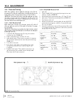
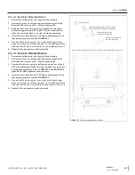
Page 30: ...move from firebox 9 Remove and save 8 screws securing the control board Lift the control board out of the firebox being careful not to damage the sealing gasket underneath 7 4 2 Control Board Installation 1 Place the control board in the firebox aligning the holes in control board with the holes and alignment screws in firebox bottom VERIFY SEALING GASKET IS IN PLACE Secure the control board with ...

Page 31: ...tion against shock hazard and should be plugged directly into a properly grounded three prong receptacle Do not cut or remove the grounding prong from this plug 8 1 Electrical Specifications This appliance when installed must be electrically grounded in accordance with local codes or in the absence of local codes with the National Electrical Code ANSI NFPA 70 or the Canadian Electrical Code CSA C2...

Page 32: ...ey are in the same room as the appliance Toddlers young children and others may be susceptible to accidental contact burns A physical barrier is recommended if there are at risk individuals in the house To restrict access to a fireplace or stove install an adjustable safety gate to keep toddlers young children and other at risk individuals out of the room and away from hot surfaces OPERATING INSTR...

Page 33: ... UP and DOWN arrows to turn the pilot on demand ON or OFF then press SELECT A single beep will be emitted from the control module indicating pilot on demand feature has been activated A double beep will be emitted from the control module indicating the pilot on demand feature has been deactivated SetupKomfort8K1ControlModule AdditionalDiagnosticInformation 9 6 Komfort 8K1 Control System Ignition S...

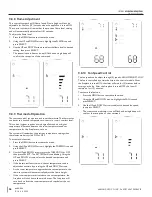
Page 34: ...le mode when the remote is ON if no buttons are pressed within 5 seconds Press any button to resume full functionality In idle mode only active functions will show on the screen 9 8 2 Standby Mode The remote control will go into a standby mode if no buttons are pressed within 5 minutes Press the POWER button to reactivate the remote control to ON mode Active functions will be displayed once in ON ...

Page 35: ...pliance With the system in the ON position press the remote control POWER button to turn OFF the appliance Functions AUX1 AUX2 and Pilot on Demand can be accessed when the remote control is OFF Only active functions will be displayed when the remote control is OFF The transmission indicator icon will flash and a single beep will confirm the reception of the command 9 8 7 Pilot Ignition Selection I...

Page 36: ...function 1 Press the MENU button to activate the menu 2 Using the UP and DOWN arrows highlight the THERMO icon and press SELECT 3 Use the UP and DOWN arrows to turn the THERMO ON or OFF then press SELECT The SET TEMP will start blinking Using the UP and DOWN arrows select the desired temperature and press SELECT If the thermostat function is on the set temperature can be adjusted at any time by pr...

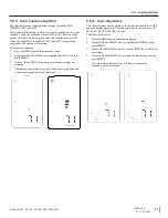
Page 37: ...he UP and DOWN arrows highlight the AUX1 icon and press SELECT 3 Use the UP and DOWN arrows to adjust to desired light kit intensity The transmission indicator icon will flash and a single beep will confirm the reception of the command 9 8 12 Timer Adjustment This control system has the option to set a timer function to turn OFF the main burner operation The timer operates in increments of 15 30 4...

Page 38: ...essure to ensure it is between the minimum and maximum recommended pressure settings TABLE 10 1 4 Turn off burner and pilot 5 Disconnect hose and tighten the inlet IN pressure tap by turning screw clockwise Screw should be snug Do not over tighten 6 Relight pilot and burner Then reattach manometer to the inlet pressure tap A to verify the tap is completely sealed Manometer should read no pressure ...

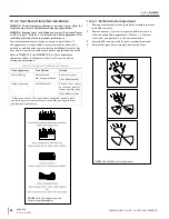
Page 39: ...g may be necessary Regardless of venturi orientation closing the air shutter will achieve a desired yellow flame but may produce soot on the glass Opening the air shutter will cause a short blue flame that may lift off the burner Slight adjustments to the venturi opening will create dramatic results Adjust at slight increments until desired look is achieved NOTE If soot is present on the logs chec...

Page 40: ...replace to burn for 15 minutes before making any adjustments 1 Remove the safety barrier and glass frame assembly to access the baffle restrictor 2 Remove and save 1 screw to adjust the baffle restrictor to achieve desired flame appearance Position 1 is the least restriction and position 5 is the most restriction 3 Secure baffle restrictor with 1 screw previously removed 4 Reinstall the glass fram...

Page 41: ...ication 1 Remove the safety barrier and the glass frame assembly 2 Remove 3 screws at the firebox back wall securing the baffle Remove baffle to access the 4 102mm exhaust pipe 3 Remove the restrictor plate by pulling it down and out of the 4 102mm exhaust pipe Make necessary modifications to achieve desired flame appearance Refer to TABLE 10 4 and FIGURE 10 5 page 40 for flame appearance adjustme...

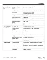
Page 42: ... in this manual to determine that all wiring connections are secure and correct Control module selector switch not set properly Verify the ON OFF REMOTE selector switch is ON mode or REMOTE mode Gas supply turned off Check remote shut off valves from the appliance Usually there is a valve near the main gas line There may be more than 1 valve between the appliance and main gas line LP NG switch on ...

Page 43: ...thermostat operation is turned OFF Pilot and burner extinguish while in operation No propane in tank Check propane tank Refill if necessary Incorrect glass assembly installation Refer to section 7 2 GLASS FRAME ASSEMBLY on page 28 Incorrect vent cap installation Adjust if necessary Vent cap blockage Remove debris if necessary Improper pitch on horizontal venting 1 4 6mm rise for every 12 305mm of ...

Page 44: ...ent system Check the vent pipes for leaks and the vent cap for debris Repair the vent pipes or remove debris from vent cap if necessary No reaction to command Battery back batteries or remote control batteries low Replace batteries No communication between remote control and control module Reprogram remote control to Komfort 8K1 module Refer to section 9 2 INITIALIZE THE KOMFORT 8K1 CONTROL SYSTEM...

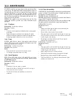
Page 45: ... provided with installation Refer to section 6 0 VENTING on page 21 Performed by Qualified Service Person Frequency Annually Action Examination of the vent system is required Inspect the condition of vent and vent terminal for sooting or obstruction and correct if present The flow of combustion and ventilation air must not be obstructed CAUTION Do not operate appliance with the glass assembly remo...

Page 46: ...s and other components for leaks Inspect the operation of the flame safety system Pilot or Flame rectification device Visually check pilot light when in operation Inspect and ensure the lighting of the main burner occurs within 4 seconds of the main gas valve opening Check for faulty or incorrect wiring and correct or replace as necessary Inspect primary air openings burner ports for blockage espe...

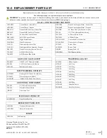
Page 47: ...Toggle Switch Harness NCK LX22L D Conversion Kit Natural Gas DEX MWH Main Wire Harness LCK LX22L D Conversion Kit Propane DEX 191 Pilot Assembly Natural Gas LX22 035 Burner Plate DEX 191 1 Pilot Assembly Pilot Assembly Propane LX22 035S Burner Tube DEX RC3 Dexen Transmitter Remote Control DEX BP Battery Pack 6V 700 094P 018 NG Pilot Orifice DEX WRH Wall Remote Holder 700 095P 012 Propane Pilot Ori...

Page 48: ...esult of but not limited to improper chimney venting installation will also render this warranty void 7 This warranty does not cover installation and operational related problems such as environmental conditions nearby trees buildings hilltops mountains inadequate venting or ventilation excessive offsets negative air pressures caused by any mechanical systems 8 Chimney components and other Non Hus...

Page 49: ......

Reviews: