background image

BSD1-xxxP-06.99-GB

Page 5

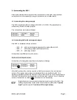
3. Connecting the SD1

This section deals with the layout of the connections on the SD1. The electrical
connection has to be made by a plug-in connection acc. to DIN 43650.

3.1 Connecting the voltage supply

The SD1 is operated with an voltage of 24 VDC or 12 VDC. The adjustment is
achieved by means of solder jumpers.

The connections are made as follows :

Terminal 1

+24 VDC

(brown)

Terminal 2

GND

(white)

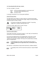
3.2 Connecting SD1 with rectangular output.

The SD 1 is available in three versions:

- SD1 – R

with two rectangular signals with a pulse offset of 90°.

- SD1 – I

with analog output (0-20 mA/4-20 mA)

- SD1 – K

with relay contact

Connections are different in each version.

Option with rectangular output:

Connection of rectangular output has to be made on clamps.

Terminal 3

Channel 1

(green)

Terminal

Channel 2

(yellow)

If the SD1 works with a volume counter, which has 2 sensors, it is a 2-channel
version. The square wave pulses are displaced from one another by 90°. It is
therefore possible to detect the direction. This is referred to as a two channel layout.
If the SD 1 works with a volume counter, which has only 1 sensor, it is a 1-channel
version. Connection on clamp          (channel 2) is not necessary.

+

Single channel or two channel connection must be set on the SD1. The
settings required are made under menu reference „

08

“ at the 

“counter

input” 

position (see 

4.1 overview of the input values

).

Summary of Contents for SD 1

Page 1: ...S D 1 O p e r a t i n g I n s t r u c t i o n s Volutronic ...

Page 2: ...easurement activated 8 3 6 How is the volume measurement activated 9 3 7 Error display 10 4 SD1 PROGRAMMING 11 4 1 Overview of the input values 12 4 2 What must be programmed when connecting a volume counter 13 4 3 How to change time on flow display 15 4 4 How to find out the flow rate 16 4 5 What must be programmed when connecting the relay outputs 17 4 6 What must be programmed when connecting t...

Page 3: ...e appropriately qualified This qualification can be obtained by appropriate training or instruction Such personnel must be familiar with the contents of these operating instructions During all operations the relevant national regulations relating to safety precautions in the work place and where applicable internal regulations of the operator must be observed even if these are not detailed in thes...

Page 4: ...ier card must be removed from the plug socket The plug in display unit is freely programmable All necessary settings can be achieved with two keys The programmed data is stored on an EEPROM and therefore saved in case of power failure As an option the plug in display is available with an analogue output 0 20 mA 4 20 mA proportional to flow rate The square wave signal is then not applicable The plu...

Page 5: ...t 0 20 mA 4 20 mA SD1 K with relay contact Connections are different in each version Option with rectangular output Connection of rectangular output has to be made on clamps Terminal 3 Channel 1 green Terminal Channel 2 yellow If the SD1 works with a volume counter which has 2 sensors it is a 2 channel version The square wave pulses are displaced from one another by 90 It is therefore possible to ...

Page 6: ... mA are available for signal selection The selection is carried out by programming the SD1 under menu reference 8 at the Analogue output position The functions are set using 0 or 1 see 4 1 Overview of the input values How does the analogue output function The function of the analogue output can be freely selected i e it can be assigned to the measurement parameters of flow rate or volume For adjus...

Page 7: ...current is 1A Connection of relay contact has to be made on clamps Terminal 3 Relay 1 green Terminal Relay 2 yellow How do the relays operate The function of the relays can be set as required i e each relay can be allocated to the flow rate or volume measurement parameters An on and an off switching value can be programmed for each relay The relay switches when the switch on value is exceeded When...

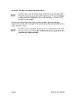
Page 8: ...be adjusted by 0 and the volume by 1 see 4 1 for overview of input values As soon as a medium flows through the volume counter a flow rate indication appears No special action is required The instantaneous flow rate is indicated as a rule in litres per minute The SD1 must be adjusted to the actual volume counter that is connected The procedure is given in section 4 2 What must be programmed when c...

Page 9: ...e signal has been given a summation will be made To programm limiting frequency under menu 10 you have to take the volume counter s impulse frequency in hertz Hz Usually the limiting frequency has to be set to 0 000 Connection of release signal output has to be made on clamps Terminal summation enable yellow If there is a voltage of 24 V at the enable input summation of the volume commences The me...

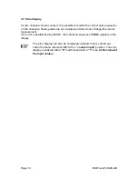
Page 10: ... counted and thus do not change the volume measurement If an error is established by the SD1 the character sequence FAUL appears in the display The error display can also be completely isolated This is carried out under the menu reference 08 at the counter input position The error display is enabled with a 0 and blocked with a 1 see 4 1 Overview of the input values ...

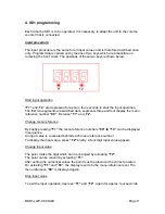
Page 11: ...ed dark segments three and four display the menu reference number 00 Release T1 and T2 Change menu reference By briefly pressing T1 the menu reference numbers 00 to 10 can be displayed in sequence An input value is concealed behind each menu reference number To display the input value press T2 briefly A four digit input value appears Change input value The point marks the digit which can be change...

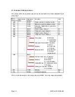
Page 12: ...in value Relay 1 l m 04 9999 Drop out value Relay 1 l m 05 9999 Pull in value Relay 2 l m 06 9999 Drop out value Relay 2 l m 07 0000 Time base 0 Minute 1 Alternative time base Alternativ time base 0 Second 1 Hour Display 0 Flow rate 1 Volume Measurement 0 Gate time 1 Period measurement 08 0000 Counter input 0 2 channel 1 1 channel Display 0 Normal 1 180 Rotation Analog Relay 0 Analogue output 1 Re...

Page 13: ...cm 3 XXX0 2 channel VC 5 Sp Gr Iron 5 222 cm 3 XXX0 2 channel VC 10 Sp Gr Iron 10 48 cm 3 XXX0 2 channel VCA 0 2 Aluminium 0 200 cm 3 XXX1 1 channel VC 0 2 AL Aluminium 0 245 cm 3 XXX0 2 channel VCA 2 Aluminium 2 000 cm 3 XXX1 1 channel VC 0 2 JR High grd St 0 200 cm 3 XXX0 2 channel VC 1 JR High grd St 1 000 cm 3 XXX0 2 channel VC 5 JR High grd St 5 000 cm 3 XXX0 2 channel VCL 0 1 PA B High grd S...

Page 14: ...cond minute and hour to change time on flow display by adjusting menu 07 Setting the time base Time base Input value Menu reference 07 Minutes XX00 Minutes XX10 Seconds XX01 Hours XX11 The X characters in the Input value Menu reference 07 column are of no significance in setting the time base ...

Page 15: ...Hz are not processed The measurement of period duration enables very fast measuring If the flow values fluctuate greatly the digital damping filter makes a smoothing and thereby a calming of the flow indicating unit possible A digital filter can be activated under the menu reference 02 The higher the input value the greater the filter effect Programmed value 0000 no filter effect Programmed value ...

Page 16: ... open function On reaching the switch on value the contact is closed Example Switch on value pull in 2 500 Switch off value drop out 9999 The relay contact is switched when the switch on value is exceeded The switch off value of 9999 has the consequence that only the switch on value is evaluated The relay is not disconnected when the switch off value is reached Normally closed function On reaching...

Page 17: ...ment A 1 is inserted under the menu reference 07 This takes place at the position designated Display see 4 1 Overview of the input values Signal selection Menu reference 08 Analogue output 0XXX 0 20 mA 1XXX 4 20 mA The digits identified with an X in the Menu reference 08 column are of no significance to the setting procedure The maximum value is entered under the menu reference 01 maximum analogue...

Page 18: ...th approx 60 mm IP 65 ca 0 12 Kg Angled connector DIN 43650 4 pins polarized Analogue outputs Option Current output 0 20 mA 4 20 mA load 250 Ohm 18 28 VDC power supply load 50 Ohm bei 10 VDC power supply Resolution 10 bit short circuit proof Pulse output Pulse amplitude Pulse shape with symm Output signal Pulse offset between two channels Output power channel Incremental signal Approx 0 8 x supply...

Page 19: ...Identification for programs V volume measurement only with version SD1 I or SD1 K volume measurement with SD1 R on request 24 24 VDC Power supply 12 12 VDC Power supply R Square wave signals incremental signal I Current output 0 20 mA 4 20 mA K Relay outputs ...

Page 20: ...nnections Version SD1 I 24 PIN 1 UB PIN 2 GND PIN 3 Analogue output 0 4 20 mA PIN Enable summation Connections Version SD1 I 24 V PIN 1 UB PIN 2 GND PIN 3 Analogue output 0 4 20 mA PIN Enable summation Connections Version SD1 K 24 PIN 1 UB PIN 2 GND PIN 3 Relay 1 PIN Relay 2 Connections Version SD1 K 24 V PIN 1 UB PIN 2 GND PIN 3 Relay 1 PIN Enable summation 1 2 3 1 2 3 1 2 3 1 2 3 1 2 3 ...

Reviews: