2
1
Periodically clean the equipment casing using a
soft cloth moistened with neutral and non-
aggressive detergents and dry with a dry cloth.
5.2
Installation instructions
Level 1 operator:
trained and informed
operator able to use the equipment in
normal operating conditions and for simple
maintenance.
Equipment:
-
Flat screwdriver
-
x2 keys 13 mm
-
Allen 6 mm
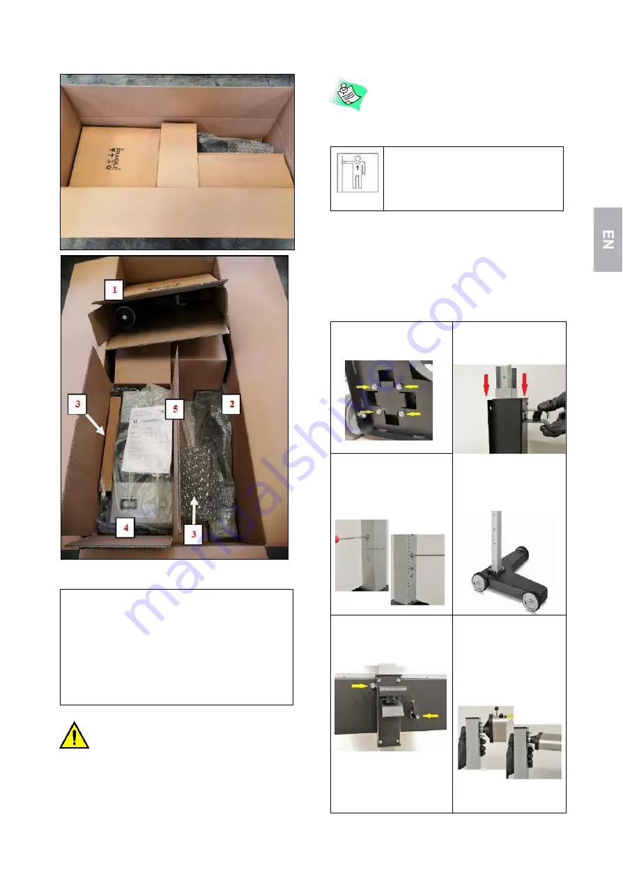
Within the packaging there are the following parts:
1.
Box containing the base
2.
Column group
3.
Mirror or laser visor
4.
Optical camera
5.
Maintenance and operating manual
6.
Certification of EC Conformity
7.
Mounting accessories
If there is damage or missing items, or if there are
defects or damages, do not try to repair the
equipment but contact the service center by
reporting the model, code and serial number of the
equipment (see Figure2.2.1. License plate data label).
Store the package, including the original packaging material,
in case you need to ship the product to be repaired.
The following steps describe the operating assembling
sequence.
1.
Insert the base into
the column using the 4
nuts out of its seat
2.
insert the sliding system
3.
Insert the second half of
the column and fix it with
the 2 lateral screws
4.
Position the structure
vertically, checking the
correct
orientation
between
base
and
column.
5.
Take the optical box and
fix it with the screw and
lever to the structure
6. Remove the visor from
the box and screw it to
the support block. Then
tighten through the hole
in the viewer.
Assembly is the same for
mirror or laser visor.
Summary of Contents for 505.003.170
Page 1: ...Ita Eng Deu Fra Es Pt Kraftwerk Group www kraftwerktools com 505 003 170...
Page 2: ...ITALIANO 3 16 ENGLISH 17 30 DEUTSCHE 31 42 FRAN AIS 43 56 ESPA OL 57 70 PORTUGU S 71 83...
Page 16: ...16...
Page 30: ...30...
Page 56: ...56...
Page 70: ...70...
Page 84: ......


