6 Installation, removal
6.3 Mounting the electronic unit to the wall
Notice
When the space is limited, mounting is also possible without a housing cover and without a seal with
cable entries.
1
2
3
4
5
6
117
117
3
117
117
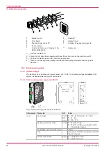
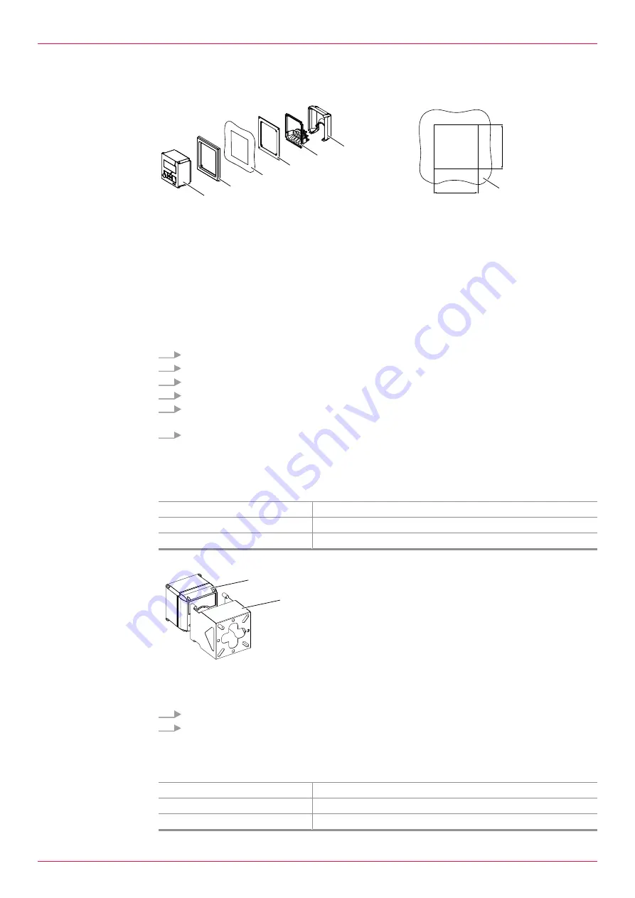
1
Electronic unit
2
Front frame
3
Control cabinet (section)
4
Sealing frame
5
Seal with cable entries
6
Housing cover
Requirement:
ü
Control cabinet with plate thickness 0.5 - 5.0 mm
ü
Mounting depth min. 80 mm
1.
Create a control cabinet section.
2.
If the space is limited, remove the housing cover
6
and seal with cable entries
5
.
3.
Slide the front frame
2
from behind onto the electronic unit
1
.
4.
Place the electronic unit with the front frame from the front into the control cabinet section.
5.
Slide the sealing frame
4
from behind onto the electronic unit. In the process the sealing surface
must point to the front.
6.
Fasten the front frame
2
and sealing frame
4
using the 4 supplied screws and wedge lock wash-
ers. Carefully tighten with 1 Nm torque.
ð
The electronic unit is ready for the connection of the cables.
6.3 Mounting the electronic unit to the wall
Personnel qualification:
o
Electrician
Personal protective equipment:
o
Work clothing
Aids:
o
KRAL tool set
For wall mounting a universal mount is available as an accessory
Ä
2
1
1
Electronic unit
2
Universal mount
Requirement:
ü
Universal mount mounted to the wall
ü
All cables have been shortened and connected
1.
Slide the electronic unit
1
into the universal mount
2
.
2.
Fasten the electronic unit using the supplied screws, washers and wedge lock washers.
ð
The electronic unit is ready to operate after the power supply has been switched on.
6.4 Mounting the electronic unit at the pipe/flowmeter
Personnel qualification:
o
Electrician
Personal protective equipment:
o
Work clothing
Aids:
o
KRAL tool set
Operating instructions
OIE 15en-GB Edition 2020-03
13


