background image

Revision 2 

Wireless Full Bin Alarm 

Page | 5 


Kramble Industries Inc. is not responsible or liable for indirect, special, or consequential damages arising out of or in connection 
with the use or performance of the product or other damage with respect to any economic loss, loss of property, loss of revenue 
or profit, or costs of removal, installation, or reinstallation. 

S

SS

Sensor

ensor

ensor

ensor    P

P

P

Probe

robe

robe

robe    

To install/change the battery, simply unscrew the top half off the Sensor Probe to reveal the circuit 
board and battery assembly. Unclip the battery connector and slide the battery out of the cable ties 
to remove. Insert the new battery in and clip the connector on. Perform the self-test described on 
page 7. Reassemble. 

Antenna Mounting

Antenna Mounting

Antenna Mounting

Antenna Mounting    

The sensor probe connects to an external antenna to be mounted at the top of the auger outside of the 
bin.  Included are two options for mounting the antenna: a #10 self-drilling screw for attaching the 
antenna bracket directly to the auger or a magnet on the antenna bracket.  Mount the antenna bracket 
in the best position possible such that the antenna has a direct line of sight to the receiver.  Do not point 
the antenna at the receiver – reception will be better when the antenna’s side faces the receiver. 

General Operation 

General Operation 

General Operation 

General Operation     

Receiver Console

Receiver Console

Receiver Console

Receiver Console    

The Receiver Console is powered by 12 volts DC and is equipped with a Power On/Off button 
and a Cancel Alarm (CAN) button on the front of the case. When the Power On/Off button is 
pressed, the red LED will light indicating normal operation. Press the Power On/Off button 
again to turn power off. 


95dB Alarm 

95dB Alarm 

95dB Alarm 

95dB Alarm 

Buzzer

Buzzer

Buzzer

Buzzer    

+12V Power 

+12V Power 

+12V Power 

+12V Power 
Connector

Connector

Connector

Connector    

Alarm LED Indicator 

On/Off Button & Power 

On/Off Button & Power 

On/Off Button & Power 

On/Off Button & Power 
On Indicator (red)

On Indicator (red)

On Indicator (red)

On Indicator (red)    

Probe Low Battery Indicator 
(green) – Probe battery 
needs replacing  

F

FF

FBA Cancel Push 

BA Cancel Push 

BA Cancel Push 

BA Cancel Push 

to silence alarm 

to silence alarm 

to silence alarm 

to silence alarm 
Learn Control 

Learn Control 

Learn Control 

Learn Control –

–    

hold during 

hold during 

hold during 

hold during 
power

power

power

power----up to 

up to 

up to 

up to 

match to a 

match to a 

match to a 

match to a 
transmitter

transmitter

transmitter

transmitter    

Receive/Learn (yellow) 
– Data receiving from 
transmitter/system in 
learn mode  

Summary of Contents for XLOR Series

Page 1: ...vice that helps prevent overfilling of grain bins by activating an alarm when the grain Sensor Probe is activated The Sensor Probe which operates at 915 8 MHz FM transmits securely encoded information to the Receiver which then decodes the information and alerts the user that the bin is full The Sensor Probe and Receiver are designed to operate within 300 but actual range is dependent on operating...

Page 2: ...f Contents Table of Contents Table of Contents Table of Contents Specifications 1 FCC 2 Industry Canada 2 Overview 3 Mechanical Installation 4 Receiver Console 4 Sensor Probe 4 Electrical Installation 4 Receiver Console 4 Sensor Probe 5 Antenna Mounting 5 General Operation 5 Receiver Console 5 Sensor Probe 7 Sensor Self Test 8 Sensor Angle Setup 8 Limited Warranty 9 Table of Figures Table of Figur...

Page 3: ...ators Internal System Battery Test Case Size 3 dia x 13 long Range 300 depending on environment Antenna External 3 15 Flexible Tuned Security Code Preprogrammed Unique Identifier Environment Weatherproof Receiver Power in 12 VDC Standby Current 40mA Alarm Current 200mA Case Size 8 x 4 8 x 2 5 Power Input 15 16ga 2 conductor wire with plug and lock connectors Indicators Power On Red LED Transmitter...

Page 4: ... equipment OFF and ON the user is encouraged to try to correct the interference by one or more of the following measures Reorient or relocate the receiving antenna Increase the separation between the equipment and receiver Connect the equipment into an outlet on a circuit different from that to which the receiver is connected Consult the dealer or an experienced radio TV technician for help Indust...

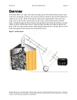
Page 5: ...cates when the grain level in the bin is reaching its maximum The system consists of a Receiver Console with audible and visible alarms a Sensor Probe that hangs into the grain bin suspended from the spout of an auger and an antenna that connects to the sensor probe and is mounted at the top of the auger The battery powered Sensor Probe is fully sealed and communicates wirelessly via radio frequen...

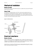
Page 6: ...ng kit contains a 12 chain a U bolt two strap plates four hex nuts four flat washers and two quick link connectors Drill two holes 1 3 8 apart in the spout and attach the U bolt as shown in the following figure Use a quick link to attach the chain to the U bolt and the second quick link to attach the chain to the Sensor Probe The U bolt may be mounted on the inside of the spout if space is limited...

Page 7: ... receiver Do not point the antenna at the receiver reception will be better when the antenna s side faces the receiver General Operation General Operation General Operation General Operation Receiver Console Receiver Console Receiver Console Receiver Console The Receiver Console is powered by 12 volts DC and is equipped with a Power On Off button and a Cancel Alarm CAN button on the front of the c...

Page 8: ...e Sensor Probe battery needs to be replaced Once activated the green LED will remain on until the receiver is powered off FBA Receiver Console Self Test To test the Receiver Console alarm light and siren hold the cancel button for six seconds while the Full Bin Alarm is powered on Once tested the alarm will shut off when the cancel button is released The Receiver power may be turned off when not i...

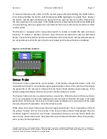
Page 9: ...rd Factory default systems are set by default so that the Learn function is Enabled and the Erase function is Disabled Figure 3 Learn Erase Function Sensor Probe Sensor Probe Sensor Probe Sensor Probe The Sensor Probe is powered by one 9v battery If the battery voltage falls below 7 volts the transmitter will transmit a Low Battery signal approximately once per hour which will illuminate the green...

Page 10: ...he threshold To exit test mode hold the button again until the yellow LED remains off The Full Bin Alarm Sensor Probe will not transmit a signal while in test mode Ensure that the LEDs are not lit before reassembling the sensor Up to eight Sensor Probes can communicate to the same Receiver Console as long as the Receiver Console has learned the probes security codes Sensor Angle Setup Sensor Angle...

Page 11: ...mental policy at Kramble Industries Inc All customers can rely upon and expect to receive prompt efficient and courteous service on all Kramble Industries Inc manufactured equipment from each and every employee of the organization Kramble Industries Inc with its office at 102 2750 Faithfull Avenue Saskatoon SK warrants To the Original Purchaser User each product manufactured by Kramble Industries ...

Page 12: ...per installation re designing of assemblies ignorance or through any other cause beyond the control of the company 3 The warranty does not cover products of other manufacturers beyond such warranty as may be made by such manufacturer 4 The warranty shall not apply to normal maintenance services or to deterioration of appearance of items due to normal use and exposure 5 The warranty shall not apply...

Reviews: