background image

Using the 3G-SDI Mini Optical Set 


5

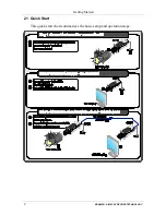
5  Using the 3G-SDI Mini Optical Set 

This section describes how to: 


Connect the detachable optical 3G-SDI Mini Optical


Transmitter/ Receiver 

(see section

 5.1


Avoid pitfalls when using the 

613T

 and 

613R

 (see section

 5.2

5.1  Connecting the 3G-SDI Mini Optical


Transmitter/Receiver Set 

To


connect the 

613T 

3G-SDI Mini Optical transmitter 

with the 

613R 

3G-SDI 

Mini Optical Receiver

, as the example in 

Figure 2

 illustrates, do the following: 

1.  Connect the BNC connector of the SDI Source (for example, a camera) 

directly

1

 to the

 613T

 BNC connector. 

2.  Plug the 5V power adapters to the transmitter and to the receiver, and 

connect the adapters to the mains electricity. 

The blue LED lights. 

3.  Connect the 

613R

 BNC connector 

directly

1

 to the BNC connector of the 

display device. 

4.  Remove the protective cover from the optic fiber ST connector on the 

613T

 and connect to the fiber optic cable

2


5.  Remove the protective cover from the optic fiber ST connector on the 

613R

 and connect to the other side of the fiber optic cable. 

6.  Turn ON the power on the source and the display devices. 


1 Avoid using any intermediate cable which may result in signal quality deterioration 
2 Use glass single-mode fiber optic cable with 1310, 1550nm bandwidth on  ST connectors. You can also use  multi-mode 
fiber optic cable 

Summary of Contents for 613R

Page 1: ...Kramer Electronics Ltd USER MANUAL Models 613T 3G SDI Mini Optical Transmitter 613R 3G SDI Mini Optical Receiver...

Page 2: ...itter Receiver 4 5 Using the 3G SDI Mini Optical Set 5 5 1 Connecting the 3G SDI Mini Optical Transmitter Receiver Set 5 5 2 Avoiding Pitfalls using the 613T and 613R 6 6 Technical Specifications 6 Fi...

Page 3: ...d security applications The package includes the following items 613T 3G SDI Mini Optical Transmitter and 613R 3G SDI Mini Optical Receiver Two Power adapters 5V DC Input and this user manual2 2 Getti...

Page 4: ...KRAMER SIMPLE CREATIVE TECHNOLOGY Getting Started 2 2 1 Quick Start This quick start chart summarizes the basic setup and operation steps...

Page 5: ...mission range of up to 19 miles 30 km at 3Gbps Handles SDI DVB ASI HD SDI 3G SDI Includes a latch locking mechanism for the power supply to prevent the power from disconnecting due to misuse Includes...

Page 6: ...power adapters Both units need to be connected to their external power adapter Figure 1 illustrates the power connector pinout 1 2 3 5V GND NC 4 Figure 1 Power Connector Pinout 4 Your 3G SDI Mini Opti...

Page 7: ...C connector 2 Plug the 5V power adapters to the transmitter and to the receiver and connect the adapters to the mains electricity The blue LED lights 3 Connect the 613R BNC connector directly1 to the...

Page 8: ...ure that the fiber optic cables are always stored and used away from liquid or dirt 6 Technical Specifications Table 1 includes the technical specifications Table 1 Technical Specifications 1 of the 6...

Page 9: ...nature ii Product modification orfailureto followinstructions supplied with theproduct iii Repairorattemptedrepairby anyonenot authorized byKramer iv Anyshipment oftheproduct claims must bepresentedto...

Page 10: ...or the latest information on our products and a list of Kramer distributors visit our Web site www kramerelectronics com where updates to this user manual may be found We welcome your questions commen...

Reviews: