


Introduction
1
1 Introduction
Welcome to Kramer Electronics (since 1981): a world of unique, creative and
affordable solutions to the infinite range of problems that confront the video,
audio and presentation professional on a daily basis. In recent years, we have
redesigned and upgraded most of our line, making the best even better! Our
500-plus different models now appear in 8 Groups
1
, which are clearly defined
by function.
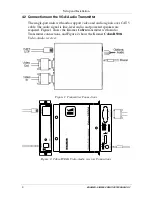
Congratulations on purchasing your Kramer
Cobra R500A
Video-Audio
receiver
and/or
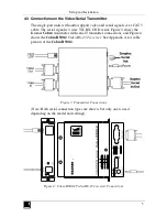
Cobra R500-2
Video-RS-232 receiver
. The Kramer
Cobra
Series System extends VGA and audio signals over ordinary Category 5
cable. This manual covers the
Cobra R500A
Video-Audio receiver
with
audio, and the
Cobra R500-2
Video-RS-232 receiver
with RS-232 serial
support. For information on the respective transmitter unit, refer to the
appropriate manual included with the transmitter.
The package includes the
Cobra R500A
Video-Audio receiver
or the
Cobra
R500-2
Video-RS-232 receiver
, an external power supply, and this user
manual
2
.
The Kramer
Cobra
series products are not compatible with Kramer non-
Cobra
series products.
2 Getting Started
We recommend that you:
Unpack the equipment carefully and save the original box and packaging
materials for possible future shipment
Review the contents of this user manual
Use Kramer high performance high resolution cables
3
. You may
also need CAT 5 cable. We recommend that you use our Kramer Pico
Skew CAT 5e cable
4
1 GROUP 1: Distribution Amplifiers; GROUP 2: Video and Audio Switchers, Matrix Switchers and Controllers; GROUP 3:
Video, Audio, VGA/XGA Processors; GROUP 4: Interfaces and Sync Processors; GROUP 5: Twisted Pair Interfaces;
GROUP 6: Accessories and Rack Adapters; GROUP 7: Scan Converters and Scalers; and GROUP 8: Cables and Connectors
2 Download up-to-date Kramer user manuals from the Internet at this URL: http://www.kramerelectronics.com
3 The complete list of Kramer cables is on our Web site at http://www.kramerelectronics.com
4 In addition, you may also need 1/8” (3.5mm) audio cable with RCA jacks, 1/8” (3.5mm) serial cable with DB9 connector,
and Video cable with HD15 connectors
Summary of Contents for Cobra R500-2
Page 13: ...11...


