background image

KRAMER:  SIMPLE CREATIVE TECHNOLOGY


Overview 


3  Overview 

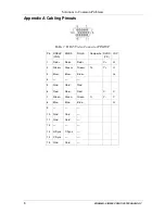
CAT 5/5e/6 cabling for this product must be pinned to the TIA-EIA T568B 

wiring specification (see appendix A). We also highly recommend that all 

CAT 5 cables be pre-terminated and tested. Cables terminated on-site or in an 

existing infrastructure should be tested before use to ensure compliance with 

the TIA-EIA T568B specification. Using incorrectly terminated CAT 5 cables 

can damage this product. 
We recommend using our Kramer 

Cobra

 ultra low skew cable—

BC-HDTP


(solid bulk) or 

BCP-HDTP

 (solid plenum bulk)—available in lengths of 700' 

(210m) and 1300' (390m). 
Our Kramer 

Cobra

 series products are compatible with CAT 5/5e/6 data 

cabling as well as skew free CAT 5/5e cabling manufactured for video 

applications. Note that some skew free CAT 5 is specific to a particular 

vendor and is not compatible with our products. Ensure any skew free CAT 5 

cable is non-proprietary prior to purchase / installation. CAT6 cable, due to 

the manufacture method, can exhibit much greater skew than standard CAT 

5/5e and may require skew compensation beyond what the standard product 

offers. Contact Kramer Electronics for assistance. 
Achieving the best performance means: 


Connecting only good quality connection cables, thus avoiding 

interference, deterioration in signal quality due to poor matching, and 

elevated noise levels (often associated with low quality cables) 


Avoiding interference from neighboring electrical appliances that may 

adversely influence signal quality and positioning your 

Cobra R500A / 

R500-2


in a location free from moisture and away from excessive sunlight 

and dust 


Caution

 – No operator-serviceable parts inside unit. 


Warning

 – Use only the Kramer Electronics input power 

wall adapter that is provided with this unit

1


Warning

 – Disconnect power and unplug unit from wall 

before installing or removing device or servicing unit. 


Warning

 –This equipment is not intended for, nor does it 

support, distribution through an Ethernet network. Do not 

connect  these  devices  to  any  sort  of  networking  or 

telecommunications equipment! 


1 For example: model number AD2512C, part number 2535-000251 

Summary of Contents for Cobra R500-2

Page 1: ...Kramer Electronics Ltd USER MANUAL Models Cobra R500A Video Audio receiver Cobra R500 2 Video RS 232 receiver...

Page 2: ...hnical Specifications 10 Figures Figure 1 Transmitter Connections 4 Figure 2 Cobra R500A Video Audio receiver Connections 4 Figure 3 Transmitter Connections 5 Figure 4 Cobra R500 2 Video RS 232 receiv...

Page 3: ...2 Video RS 232 receiver an external power supply and this user manual2 The Kramer Cobra series products are not compatible with Kramer non Cobra series products 2 Getting Started We recommend that you...

Page 4: ...due to the manufacture method can exhibit much greater skew than standard CAT 5 5e and may require skew compensation beyond what the standard product offers Contact Kramer Electronics for assistance...

Page 5: ...nections via the 1 8 3 5mm audio connector or DB9 serial connector transmitter model dependent 4 Connect the CAT 5 cable to the transmitter 5 Apply power on the transmitter The LED should light and if...

Page 6: ...t video and audio signals over CAT 5 cable The audio signal is line level audio and powered speakers are required Figure 1 shows the Kramer Cobra transmitter with Audio Transmitter connections and Fig...

Page 7: ...ND serial Figure 3 shows the Kramer Cobra transmitter with serial Transmitter connections and Figure 4 shows the Cobra R500 2 Video RS 232 receiver See Appendix A for cable pinouts of the Cobra R500 2...

Page 8: ...parts inside the Cobra R500A Cobra R500 2 All adjustments are performed externally Table 1 Cobra R500A Cobra R500 2 Configuration Settings SW Configuration Settings SW position 1 2 3 Signal Setting L...

Page 9: ...wer is ON Check input source levels from the source device Make sure the audio source is not overdriven or underdriven Audio is summed left and right for A versions If using a single channel both audi...

Page 10: ...Table 3 HD15 Video Connector PINOUT Pin RGBHV VGA RGBS RGsB Composite SVHS Y C YUV 1 Red Red Red C V 2 Green Green Green C Y Y 3 Blue Blue Blue U 4 5 Gnd Gnd Gnd 6 Red Red Red C V 7 Green Green Green...

Page 11: ...5 mm Audio Serial Connection model dependent Pin Signal Tip Serial Tx DB9 pin3 Left Audio Ring Serial Rx DB9 pin2 Right Audio Sleeve Serial GND DB9 pin5 GND Note The stereo audio input at the transmit...

Page 12: ...hms maximum REQUIRED DESTINATION IMPEDANCE Video IN 75 ohms Audio IN if any 600 ohms minimum AUDIO CHARACTERISTICS Channels Right Left summed Line Level 600 Ohm Unbalanced SERIAL CHARACTERISTICS Proto...

Page 13: ...11...

Page 14: ...or the latest information on our products and a list of Kramer distributors visit our Web site www kramerelectronics com where updates to this user manual may be found We welcome your questions commen...

Reviews: