background image

KRAMER:  SIMPLE CREATIVE TECHNOLOGY


Setup and Installation 


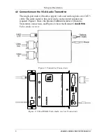
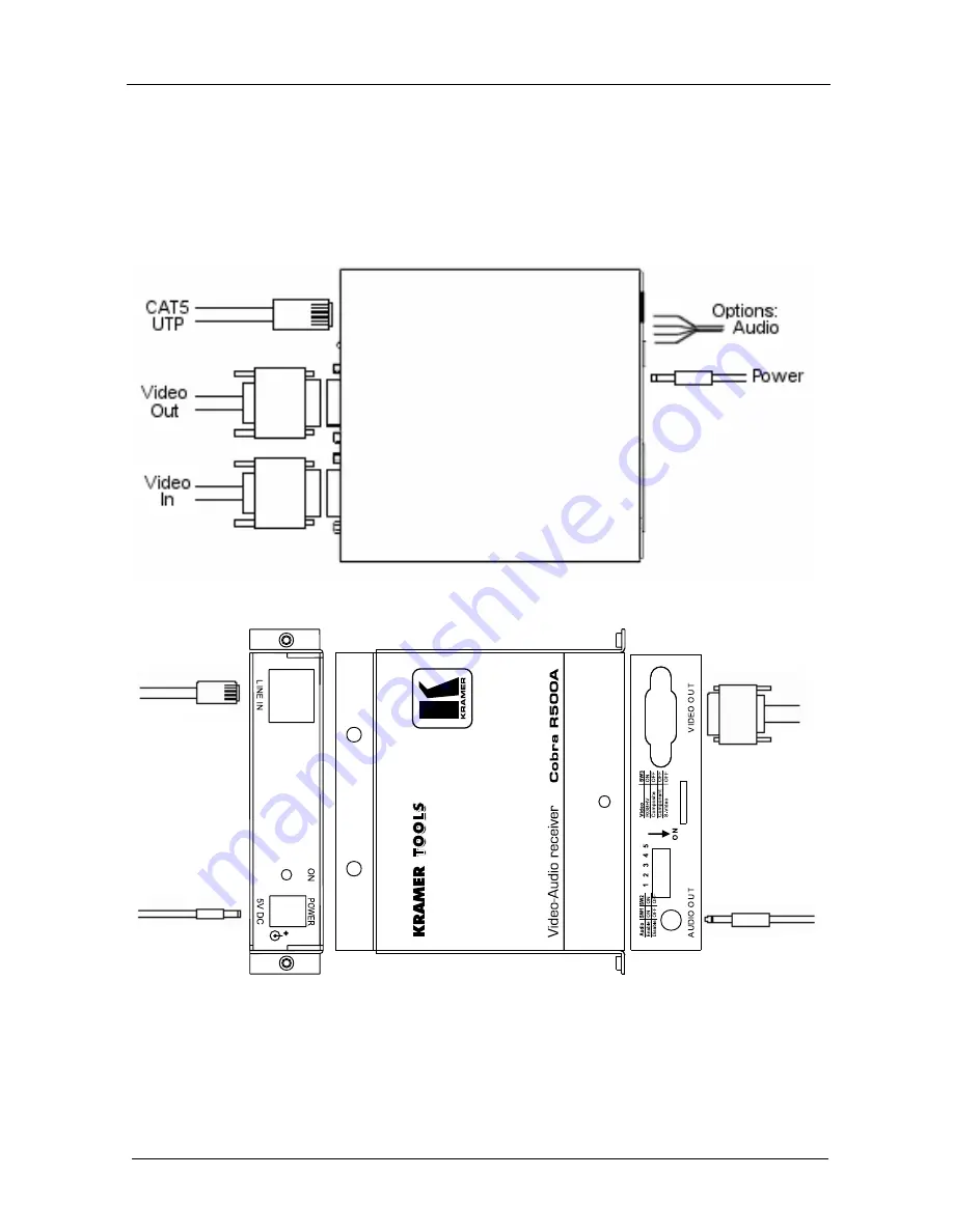
4.2  Connections on the VGA/Audio Transmitter 

The single-port units with audio support video and audio signals over CAT 5 

cable. The audio signal is line-level audio, and powered speakers are 

required. Figure 1 shows the Kramer 

Cobra 

transmitter with Audio 

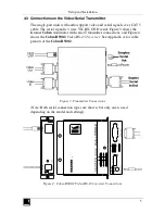
Transmitter connections, and Figure 2 shows the Kramer 

Cobra R500A


Video-Audio receiver


Figure 1: Transmitter Connections 


Figure 2: Cobra R500A Video-Audio receiver Connections 


Summary of Contents for Cobra R500-2

Page 1: ...Kramer Electronics Ltd USER MANUAL Models Cobra R500A Video Audio receiver Cobra R500 2 Video RS 232 receiver...

Page 2: ...hnical Specifications 10 Figures Figure 1 Transmitter Connections 4 Figure 2 Cobra R500A Video Audio receiver Connections 4 Figure 3 Transmitter Connections 5 Figure 4 Cobra R500 2 Video RS 232 receiv...

Page 3: ...2 Video RS 232 receiver an external power supply and this user manual2 The Kramer Cobra series products are not compatible with Kramer non Cobra series products 2 Getting Started We recommend that you...

Page 4: ...due to the manufacture method can exhibit much greater skew than standard CAT 5 5e and may require skew compensation beyond what the standard product offers Contact Kramer Electronics for assistance...

Page 5: ...nections via the 1 8 3 5mm audio connector or DB9 serial connector transmitter model dependent 4 Connect the CAT 5 cable to the transmitter 5 Apply power on the transmitter The LED should light and if...

Page 6: ...t video and audio signals over CAT 5 cable The audio signal is line level audio and powered speakers are required Figure 1 shows the Kramer Cobra transmitter with Audio Transmitter connections and Fig...

Page 7: ...ND serial Figure 3 shows the Kramer Cobra transmitter with serial Transmitter connections and Figure 4 shows the Cobra R500 2 Video RS 232 receiver See Appendix A for cable pinouts of the Cobra R500 2...

Page 8: ...parts inside the Cobra R500A Cobra R500 2 All adjustments are performed externally Table 1 Cobra R500A Cobra R500 2 Configuration Settings SW Configuration Settings SW position 1 2 3 Signal Setting L...

Page 9: ...wer is ON Check input source levels from the source device Make sure the audio source is not overdriven or underdriven Audio is summed left and right for A versions If using a single channel both audi...

Page 10: ...Table 3 HD15 Video Connector PINOUT Pin RGBHV VGA RGBS RGsB Composite SVHS Y C YUV 1 Red Red Red C V 2 Green Green Green C Y Y 3 Blue Blue Blue U 4 5 Gnd Gnd Gnd 6 Red Red Red C V 7 Green Green Green...

Page 11: ...5 mm Audio Serial Connection model dependent Pin Signal Tip Serial Tx DB9 pin3 Left Audio Ring Serial Rx DB9 pin2 Right Audio Sleeve Serial GND DB9 pin5 GND Note The stereo audio input at the transmit...

Page 12: ...hms maximum REQUIRED DESTINATION IMPEDANCE Video IN 75 ohms Audio IN if any 600 ohms minimum AUDIO CHARACTERISTICS Channels Right Left summed Line Level 600 Ohm Unbalanced SERIAL CHARACTERISTICS Proto...

Page 13: ...11...

Page 14: ...or the latest information on our products and a list of Kramer distributors visit our Web site www kramerelectronics com where updates to this user manual may be found We welcome your questions commen...

Reviews: