


Solutions to Common Problems
7
5 Solutions to Common Problems
In most cases, nearly every issue with the
Cobra
series can be resolved by
checking the CAT 5 termination and making sure that it’s pinned to the
TIA/EIA 568B wiring specification. However, there may be other problems
that cause the system to not perform as it is designed. Below are solutions to
the most common installation errors.
Problem:
No video signal at the transmitter local port or at the receiver.
Solution:
Check that both units are powered.
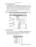
Ensure EQ adjustment switches are set correctly
Make sure the CAT 5 cable is terminated correctly per the
TIA/EIA 568B wiring specification.
Is the display device powered on and functioning?
Check to ensure display settings (resolution, refresh rate, and so
on) are compatible with input signal.
Problem:
Poor video quality.
Solution:
Have all receiver adjustments been finished?
Ensure EQ adjustment switches are set correctly
Check all cable connections
The video signal’s refresh rate may be set too high. Reset to a
lower refresh rate in your monitor-configuration menu
Problem:
Poor audio quality. (Cobra R500A only)
Solution:
Powered speakers are required. Make sure speaker power is ON
Check input source levels from the source device. Make sure the
audio source is not overdriven or underdriven.
Audio is summed left and right for “A” versions. If using a single
channel, both audio inputs must be connected at the transmitter
end for full audio gain. Audio is line level
Low Level Audio may require the 100 termination disabled.
Turn SW1 off to disable termination
Problem:
Serial communication doesn’ t work correctly. (Cobra R500-2 only)
Solution:
Are the serial devices connected properly? Are the serial
parameters correct for source/destination devices?
Are the serial cables terminated correctly? If a null-modem cable
is used, it must be placed at the receiver end.
When using RS-232 transmitters or receivers in daisy chains, CAT
5 switches, or CAT 5 distribution amps, the serial signal is a
unidirectionally broadcast mode only. In this mode, all other
Cobra CAT5 Video System devices must be the simplex serial
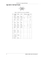
type. Cobra R500-2 use 3 wire (TX,RX,GND) signals only via the
1/8” connector (see Appendix A for pinout)
Problem:
“Green shift” or “green washout” on multimedia signals
Solution:
The standard video model is designed to function with DC
coupled signals in which the black level is referenced to 0 volts.
For five-component (RGB/H&V) AC coupled video, the Cobra
transmitter has been designed with full DC restoration capability.
Refer to the transmitter user manual.
Summary of Contents for Cobra R500-2
Page 13: ...11...


