


Kramer Electronics Ltd.
15
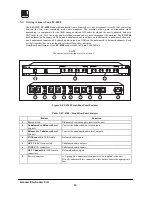
6
INSTALLATION
6.1
Rack Mounting
The FC-19, FC-4041C, FC-4042, FC-4043, FC-4044 and FC-4208 may be rackmounted in a standard 19” (1U)
EIA rack, and include rack “ears” at the ends of the front panel. To mount them, simply place the unit's ears
against the rack rails of your rack, and insert standard screws through each of the four corner holes. The FC-10
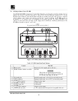
and the FC-10D can be rack mounted using a special adapter (see section 4.1). These devices do not require any
specific spacing for ventilation above or below the unit.
7
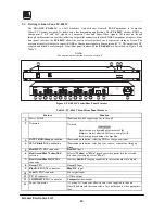
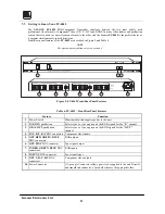
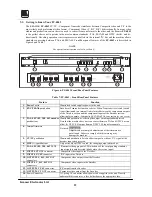
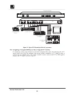
CONNECTING TO VIDEO DEVICES
Video sources and output devices (such as monitors, projectors or recorders) may be connected to the machines
through the BNC and/or 4P type connectors located on the back of the units. Unused inputs are terminated to
75ohm, and active inputs should be terminated by the connecting source. All signal connections that use more
than one cable interconnecting between devices should be of equal length. (Example: RGB cables between a
camera and the machine should be equal in length.) The signals supported by the various models are: Composite
Video, s-Video (Y/C), Component Video and Analog Red, Green, Blue and Sync signals (RGBS).
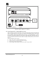
8
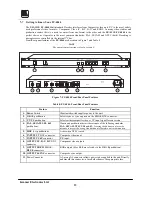
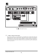
CONNECTING TO AUDIO DEVICES (FC-4208 only)
Audio sources and output devices (such as amplifiers or recorders) may be connected to the machine through
the RCA or/and XLR type connectors located on the back of the machine.
9
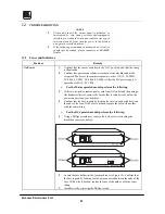
USING THE MACHINES
9.1
Powering on the Machine
NOTES
1)
The machine should only be powered on after all connections
are completed and all source devices have been powered on.
Do not attempt to connect or disconnect any video, audio or
control signals to the machine while it is powered on!
2)
The socket-outlet should be near the equipment and should be
easily accessible. To fully disconnect equipment, remove
power cord from socket.
1.
Toggle the switch on the far-left front panel to the up position. The switch will glow.
2.
Operate sources and the acceptors.
9.2
Composite/YC Video Selection (FC-19, FC-4043, FC-4044 only)
Selecting either Composite or Super video to be converted is simply done by using the Select CV/YC switch
(FC-19) or the CV/YC pushbutton (FC-4043, FC-4044).
9.3
Adjusting the HUE (FC-4043, FC-4044 only)
The term "HUE" is often used synonymously with the term "tint". It is the dominant wavelength, which
distinguishes a color or tint as red or yellow, etc. Video hue is influenced by several factors: Adjustment of the
white balance of the camera, quality of the electronic equipment which is being used, and lighting of the scene.
In the American NTSC standard, hue errors are more common than in the European PAL standard due to a
different color encoding system. The PAL system compensates for color problems and corrects wrong hues
during operation. Video color processors are needed to adjust and correct hue problems. To adjust the HUE,
simply press the HUE "
+
" or "
-
" pushbuttons, until a satisfactory picture color is achieved.
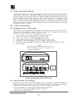
9.4
Looping (FC-4041C only)
The looping function enables the operator to connect several machines to the format interface. The operator
must always switch the termination switch of the first and middle machines to "Hi-z". The last machine’s
termination switch should always be at "75ohm" to maintain well-matched lines (of 75ohm impedance) from
the first to the last machine. Note that if the looping function is not used, the termination switch should be set to
"75 ohm".


