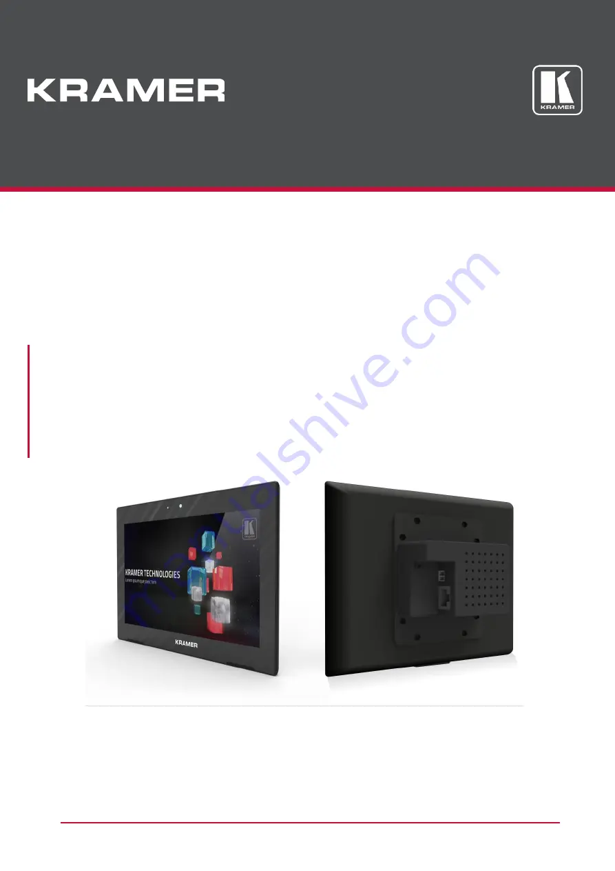
background image


P/N: 2900-300696 Rev 1 

www.kramerAV.com


USER MANUAL 

MODELS: 

KT-107

,


7” Touch Panel 

KT-107RB

,


7” Touch Panel 


Summary of Contents for KT-107

Page 1: ...P N 2900 300696 Rev 1 www kramerAV com USER MANUAL MODELS KT 107 7 Touch Panel KT 107RB 7 Touch Panel ...

Page 2: ...ing the KT 107 KT 107RB 9 Mounting the KT 107 on a Table 9 Mounting the KT 107 on a Wall 14 Connecting Options 21 Setting up the KT 107 KT 107RB 22 Initial Setup 22 Additional KT 107 Important Functions 28 Upgrading the Firmware 31 Setup your PC for Firmware Upgrade 31 Install the RockChip Driver Assistant 31 Prepare the KT 107 for Firmware Upgrade 33 Upgrade the Firmware via PC 33 Technical Speci...

Page 3: ...igital Signage GROUP 13 Audio and GROUP 14 Collaboration Getting Started We recommend that you Unpack the equipment carefully and save the original box and packaging materials for possible future shipment Review the contents of this user manual Go to www kramerav com downloads KT 107 to check for up to date user manuals application programs and to check if firmware upgrades are available where app...

Page 4: ...untry go to our recycling pages at www kramerav com support recycling Overview Congratulations on purchasing your Kramer KT 107 KT 107RB Touch Panel Throughout this manual KT 107 refers to both KT 107 and KT 107RB unless specified otherwise KT 107RB Wi Fi 5GHz frequency band range is restricted to up to 5 35GHz KT 107 is a 7 inch IPS multi touch powerful Touch Panel with 1280x800 resolution The el...

Page 5: ... Installation Powering and connectivity via a single Ethernet cable Flexible Mounting Including table and wall mounts that fit into standard market available 2 Gang in wall junction boxes Optional Connectivity Simple wireless BTLE 4 0 Bluetooth as well as connection to USB peripheral devices for either table or wall mount installations using the included USB cable Reliable Networking Seamless swit...

Page 6: ...e room lighting conditions Activity RGB LED Lights green when powered flashes green when charging the battery lights red when camera is on Camera For remote room viewing or video conferencing Microphone For audio communication recording or conferencing Speakers To output the sound Control Button Touch the Kramer logo area lightly to set the screen to sleep mode or turn it back on Press and hold fo...

Page 7: ...mediately This button is also used for firmware upgrade see Upgrade the Firmware via PC on page 33 U Button Used for firmware upgrade Press to increase KT 107 speaker volume Micro USB Port For connecting to an adjacent on wall USB device and for firmware upgrade Flat Cable Connector For connecting to the on wall mount unit see Mounting the KT 107 on a Wall on page 14 Connecting Holes For connectin...

Page 8: ...07 tabletop mount Figure 3 Tabletop Mount Front View Feature Function Screw Openings x2 For attaching the Touch Panel to the tabletop mount using the supplied M2x4 screws see Mounting the KT 107 on a Table on page 9 M5x60 Secure Screw Opening For safely securing the tabletop mount to the table from underneath see Figure 8 ...

Page 9: ... Connect to a power adapter and to the mains Cable Opening Knock out area Cable pass through area Screw Openings with Rubber Covers x2 For covering the M2x4 screws that are used for attaching the KT 107 to the tabletop mount see Mounting the KT 107 on a Table on page 9 Kensington Locker Port For securely connecting the tabletop mount to a table with a Kensington compatible locker PoE Ethernet RJ 4...

Page 10: ...ble through the opening to connect to the rear side of the KT 107 Indication Arrows Top side up shows the correct direction for mounting the on wall mount unit and for hanging the Touch Panel Screw Opening x2 For attaching the on wall mount unit to a standard in wall junction box various holes fit different standard in wall junction boxes Indication Arrows Top side up shows the correct direction f...

Page 11: ...ble is not secured and can be moved The cables connected to KT 107 can be hidden by connecting them under the table via the cable pass through opening in secure mode or they can be connected over the table thus remaining visible for both mounting modes Preparing the Table for a Secure Mount To mount KT 107 in portable mode go to Setting KT 107 on the Tabletop Mount on page 12 When mounting KT 107 ...

Page 12: ...e table To drill the M5x60 screw hole in a table 1 Measure the exact location on the surface of the table where you want to install the KT 107 2 Drill a hole in the table and cut the cable pass through opening with a saw according to the dimensions shown in Figure 6 not to scale Take care not to damage the table Kramer Electronics is not responsible for any damage caused to the table To cut the ca...

Page 13: ...KT 107 KT 107RB 11 Secure the Tabletop Mount To secure the KT 107 tabletop mount 1 Remove the rubber covers from the rear tabletop mount 2 Remove the cable cover Figure 7 Removing Cable Cover and Rubber Screw Cover 3 Place the tabletop mount on the table ...

Page 14: ... 107 on the Tabletop Mount Before you begin verify that the cable cover is removed To connect the cables and set the KT 107 on the tabletop mount 1 Connect the RJ 45 port on the tabletop mount to the PoE enabled network 2 Connect the power adapter to the Power 2 pin terminal block connector on the tabletop mount and to the mains power 3 Place the KT 107 over the tabletop mount the Touch Panel is m...

Page 15: ...th the installation process 5 Secure the KT 107 to the tabletop mount using the two M2x4 screws supplied that are inserted via the openings on the rear side of the tabletop mount 6 Replace the rubber covers to hide the screws Figure 9 Connecting to the KT 107 Rear Panel 7 Connect the Ethernet and micro USB cables by either passing the cables from underneath the table via the cable opening see Prep...

Page 16: ...The cables are passed inside the wall and then connected to the rear side of the on wall mount unit Before mounting the KT 107 on a wall you need to install a standard 2 Gang in wall junction box We recommend that you use any of the following standard 2 Gang in wall junction boxes USA 2 Gang electrical junction boxes Europe 2 Gang in wall junction box 47mm minimum depth DIN 49073 UK 2 Gang in wall...

Page 17: ...on box top side up see the indication arrows on the mount 2 Screw the 4 wall mounting screws supplied through the screw openings The on wall mount screw openings are set in different locations to fit various types of in wall junction boxes Figure 11 Installing the On Wall Mount Unit 3 Optionally insert the supplied right angle OTG USB port if you need to connect the KT 107 to an external USB devic...

Page 18: ...rnet to the Touch Panel To connect the flat cable 1 On the rear side of the KT 107 unscrew the cover and set the cover and screw aside Figure 12 Removing the Cover on the KT 107 Rear Side 2 Attach the panel mount plate top side up see arrows to the rear of the KT 107 3 Fit the connecting holes on the KT 107 to the screw holes on the panel mount ...

Page 19: ...the Panel Mount Plate to the Rear Side of the KT 107 5 Connect the flat cable between the on wall mount and the KT 107 Figure 14 Connecting the On wall Mount Flat Cable If you need to secure the KT 107 to the wall use the Kramer KT 107 OWLK purchased separately For installation instructions see Installing the On Wall Secure Lock on page 19 ...

Page 20: ...cs Ltd KT 107 KT 107RB Mounting the KT 107 KT 107RB 18 6 Hang the KT 107 on the wall by sliding the tabs on the attached panel mount plate over the grooves on the on wall mount unit Figure 15 Hanging KT 107 on the Wall ...

Page 21: ... and 2 washers To secure KT 107 to the on wall mount 1 Insert the 2 screws supplied into the screw openings and insert the washers from below This example shows the short part on top and the long part below You can attach it with the long part on top and the short part below 2 Place the short part together with the screws over the installed on wall mount unit 3 From below slide the long frame part...

Page 22: ...T 107RB 20 4 Loosely screw the top frame part to the lower frame part do not tighten the screws Figure 17 Screws Loose 5 After hanging the KT 107 on the wall Figure 14 tighten the two screws until the KT 107 is securely fixed in place Figure 18 Screws Tightened ...

Page 23: ...ing the battery for 8 hours Figure 19 Powering the KT 107 Touch Panel Connect to the local area Ethernet network Via Ethernet cable connection to the LAN RJ 45 connector Use Wi Fi if no wired Ethernet connection is available or as a fall back option KT 107 features auto sensing It detects the speed of LAN devices such as the LAN Ethernet switch the router and so on connected to KT 107 and automati...

Page 24: ...you can slide the KT 107 in place and wait for the Home page to sppear Figure 20 KT 107 Home Page Initial Setup Following installation use the Home page Settings application to perform the following initial setup tasks Setting the Date and Time on page 23 Modifying the Display Settings on page 24 Setting the Control Button on page 26 Defining Home page Password protected Exit on page 27 ...

Page 25: ... date and time 1 In the Home page click Settings Figure 21 Settings Date Time 2 Scroll down to the System area and click Date time Figure 22 Settings Automatic Date Time 3 Enable Automatic date time to derive the date and time from the network If disabled set the date and time manually 4 Select the time format ...

Page 26: ...Ltd KT 107 KT 107RB Setting up the KT 107 KT 107RB 24 Modifying the Display Settings To modify Display Settings 1 In the Home page click Settings Figure 23 Settings Display 2 Click Display Figure 9 Settings Display Setup ...

Page 27: ...out displaying status bars Define display activity Sleep set Touch Panel sleep timeout The following table defines how to access the Home page when the bars are hidden under the following conditions the Control button is enabled or disabled and the Touch Panel is or is not password protected Control Button Enabled Control Button Disabled Press the Control button The Power reset pop up screen appea...

Page 28: ...ws Press briefly to enter the KT 107 sleep mode When in sleep mode press briefly to exit Press twice to activate the camera if enabled via the Display Menu see Modifying the Display Settings on page 24 Press for 1 to 2 seconds for the pop up menu to appear and select Power off Reboot or Home page Figure 24 Using a Hidden Control Button When the Touch Panel is off turn it on again via the power but...

Page 29: ...ure 25 Control Button Activation 3 Enable or disable the control button Defining Home page Password protected Exit Password protection is used to prevent an unauthorized person from exiting an application program When the Control button is disabled this option is disabled too To enable disable password protection 1 In the Home page click Settings 2 Select Control ...

Page 30: ...nable or disable this feature see Figure 25 The protected exit password is KT 107go2home Figure 26 Password on Exit Settings Additional KT 107 Important Functions This section describes the following additional KT 107 functions About Touch Panel Page on page 29 Top Bar Functions on page 30 Lower Bar Functions on page 30 ...

Page 31: ...ouch Panel Page The About page summarizes all the Touch Panel information such as system updates To view Touch Panel information 1 In the Home page click Settings 2 Scroll down and select About touch panel The About touch panel screen appears Figure 27 About the KT 107 Touch Panel ...

Page 32: ... the KT 107 KT 107RB 30 Top Bar Functions The top bar displays various messages such as time and date battery status and so on Figure 28 Top Bar Functions Lower Bar Functions Use the lower bar functions as follows Figure 29 KT 107 Lower Bar Functions ...

Page 33: ...ding to your device type The FW upgrade tools zip file includes both Rockchip_DriverAssitant and KT FW Upgrade Tool upgrade tools 2 Copy the KT 107 Firmware Release xx or KT 107RB Firmware Release xx FW Upgrade Tool and Rockchip_driverAssistant files and unzip them to local folders on your PC Verify that the KT 107 Firmware Release xx or KT 107RB Firmware Release xx folder includes the Update img ...

Page 34: ...riverInstall tool on your PC Figure 30 Installing the Driver 4 Click Install Driver The following window appears Figure 31 Driver Installation Security Note 5 Click Install repeatedly on the next few screens until the driver is successfully installed Figure 32 Successful Installation 6 Click OK ...

Page 35: ...e Touch Panel 4 Connect the PC USB port directly to the micro USB port on the rear of the KT 107 do not use the port on the mount via a USB cable with data transfer capabilities You can connect several Touch Panels to upgrade simultaneously Carefully place the KT 107 in a way that does not cause damage to the USB cable or port Upgrade the Firmware via PC To upgrade the firmware 1 In the KT FW Upgr...

Page 36: ...nel for approximately 2 seconds and turn the power off see Setting the Control Button on page 26 4 On the rear side of of the Touch Panel press the Volume up button together with the Power button for a few seconds until the ON front panel LED dimly lights green and the 1 indication in the Connected Devices area of the FW Upgrade Tool window shows that the device is connected to the PC turns green ...

Page 37: ...process fails press and hold the Power button until the unit powers down and then restart the FW upgrade process Figure 35 Touch Panel Connected to PC 5 Click Upgrade after all the Connected Devices icons turn green The upgrade progress is displayed Figure 36 Firmware Upgrade Progress ...

Page 38: ...T 107RB Upgrading the Firmware 36 6 Wait for the green Success message to appear Figure 37 Firmware Upgrade Complete Following successful firmware installation wait for the Touch Panel to power up This process may take a few minutes ...

Page 39: ... operation Controls Hidden reset button power button volume up button Touch panel status LED flashes green during charging steady green for fully charged red for camera on Power Inputs Power over Ethernet complies with IEEE802 3af and IEEE802 3at PoE standards power supply unit Power Consumption 5V DC 3A Operating Temperature 0 to 40 C 32 to 104 F Storage Temperature 10 to 55 C 14 to 131 F Humidit...

Page 40: ... you assume all risks of loss or damage during shipment Kramer Electronics will not be responsible for any costs related to the removal or re installation of this product from or into any installation Kramer Electronics will not be responsible for any costs related to any setting up this product any adjustment of user controls or any programming required for a specific installation of this product...

Page 41: ...pening andservicing For the latest information on our products and a list of Kramer distributors visit our Web site where updates to this user manual may be found We welcome your questions comments and feedback www kramerAV com info kramerel com P N 2900 300696 Rev 1 ...

Reviews: