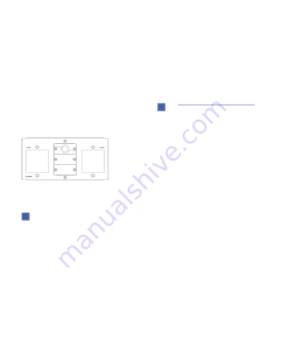
The Kramer T4F-23 Inner Frame
Congratulations on purchasing your Kramer
T4F-23
inner frame for the
TBUS-4xl
Table Connection bus.
The
T4F-23
inner frame includes:
2 openings for 2 power sockets
2 blank inserts
1 pass-through opening
Figure 1: T4F-23 Inner Frame (P/N: 80-003699)
Power Socket and Power Cord Options
Various power sockets and power cords are available to use with the
T4F-23
, as described in the
“TBUS Modular Power Socket Installation and Power Cord” Installation Instructions, supplied with
the power socket.
Each power socket comes with detailed assembly instructions.
The T-2INSERT Kit Option (80-00006699)
You can install the
T-2INSERT
kit (which includes 1 pass-through insert and a blank insert)
instead of a power socket.
Mounting the Inserts
Go to
http://www.kramerelectronics.com/support/product_downloads.asp
to
check for up-to-date user manuals and the complete list of Kramer wall plates
and module connectors.
You can rearrange or remove any of the plates mounted on the inner frame and replace them
with Kramer passive wall plates or connector modules for interfacing A/V type signals.
To mount a Kramer insert or connector module:
1. Unscrew the two screws that fasten the blank plate to the inner frame and remove the
blank plate.
2. Place the required Kramer insert over the opening, insert the two screws to fix the Kramer
insert in place, and tighten them.
Installing the Assembled Inner Frame
To install the
T4F-23
inner frame:
1. Place the assembled inner frame inside the
TBUS-4xl
enclosure.
2. Set the required height using your fingers to bring the inner frame to the desired position,
screw and tighten it in place using the height adjustment screws supplied with the inner
frame.
Connecting the Cables
When replacing blank inserts with connector inserts (for example, VGA, audio, HDMI and so on):
1. Insert the cables to their appropriate connectors from underneath.
2. Secure the cables to the tie holes on the
TBUS-4xl
.
Do not secure the cables too tightly or too loosely. Leave a small amount of slack.
After the
TBUS-4xl
is connected to mains power and the proper cables, it is ready for use.
i
i


