Your TBUS-3
5
Table 1: TBUS-3 Table Connection Bus Features
#
Feature
Function
1
Connecting Surface
See
Figure 3
and
Table 2
2
Black Anodized Lid
Covers the connecting surface, leaving the table surface neat and tidy
3
Mounting Plate Outer Rim Fits over the table surface
4
Enclosure
Inserts into the table cutout
5
Height Adjustment Screws Eight screws for adjusting the height of the connecting surface, two on
each panel
6
Rubber Protectors
Protect the table surface when mounting the unit (one on each side)
7
Locking Butterfly Screws
Tighten to lock the mounting butterfly screw (one on each side)
8
Mounting Brackets
Fit in the bracket slits after inserting the enclosure into the table – to
secure the unit to the table surface (one on each side)
9
Mounting Butterfly Screws Tighten to secure the unit to the table surface (one on each side)
10 Tie Holes
1
Anchor the self-locking ties to secure the pass-through cables to the
inside walls of the unit (6 pairs of holes, 3 pairs on the front and 3 pairs on
the rear panel)
11 Protective Rubber Guard
Protects the mounting plate outer rim during shipping. Remove before
installing unit
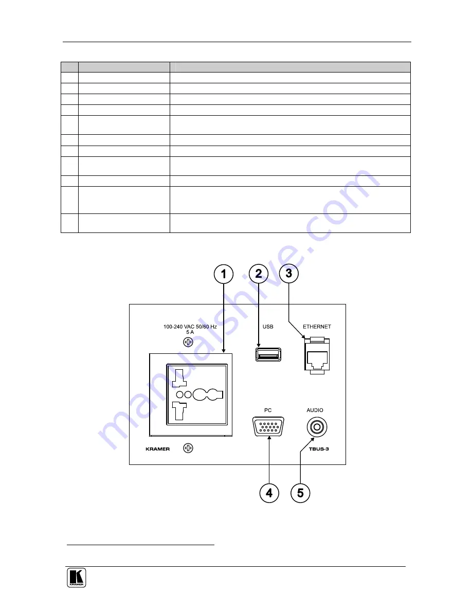
Figure 3
and
Table 2
define the connecting surface:
Figure 3: TBUS-3 Connecting Surface
1 Some versions may not include tie holes


