

Step 3: Install TP-590RXR
Install
TP-590RXR
using one of the following methods:
•
Attach the rubber feet and place the unit on a flat surface.
•
Fasten a bracket (included) on each side of the unit and attach it to a flat surface.
For more information go to
www.kramerav.com/downloads/TP-590RXR
•
Mount the unit in a rack using an optional
RK-T2B
rack adapter.
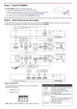
Step 4: Connect the inputs and outputs
Always switch OFF the power on each device before connecting it to your
TP-590RXR
. For best results, we recommend that you
always use Kramer high-performance cables to connect AV equipment to
TP-590RXR
.
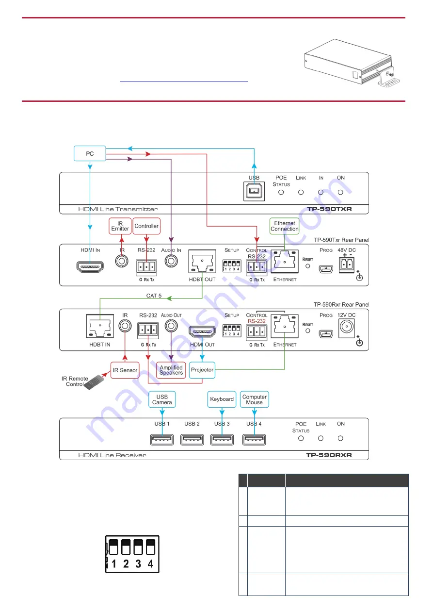
Setting the DIP Switches
Set the DIP-switches using the table on the right. The ON/OFF
positions are as follows:
•
Switch down = ON
•
Switch up = OFF
Note
: Changes to the DIP-switches only take effect on power-up.
Function
Status
1 Range
mode
Off
—Extended range (provides increased
range at a reduced bandwidth)
On
—Normal range (factory default)
2 Reserved
Off
—Factory default
3 EDID lock
Off
—Automatic EDID acquisition (factory
default)
On
—Lock (locks the current EDID so that
changes on the output do not result in
changes to the EDID)
4 Reserved
Off
—Factory default


