#
Feature
Function
1
INPUT LED
Lights when an input signal is active; flashes slowly when no input signal is detected.
2
LOOP LED
Lights on the looped device when a looped signal is in use.
3
OUTPUT STATUS LEDS
Lights when an output signal is active.
4
USB CONNECTOR
Used to import graphic images.
5
INPUT HDMI Connector
Connect to the source.
6
LOOP HDMI Connector
Connect to an additional VCO device to daisy chain additional displays.
7
HDMI OUT Connector
Connect to the displays from 1 to 8 (
VCO-8
); from 1 to 16 (
VCO-16
);
from 1 to 5 (
VCO-5UHD
); 1 (
VCO-1
).
8
SETUP DIP-Switches
For setting the last number in the machine LAN IPv4 address.
9
RESET/TEST Button
RESET (for
VCO-5UHD
,
VCO-8
,
VCO-16
), TEST (for
VCO-1
)
Press for 5 seconds to reset IP settings to factory default values.
Press briefly to enter the test pattern mode. The input signal is replaced with a test pattern
at 1080p. Press briefly again to cycle between available test patterns or return to the input
signal.
Test pattern mode is useful for initial setup of the system.
10 ETHERNET Connector
Connects to the PC or other LAN controller through computer networking.
11 Power Connector with Fuse
AC connector, enabling power supply to the unit.
12 LOOP Switch
Set LOOP switch to ON to define OUTPUT 1 as a video pass-through channel (looping the
input to an additional VCO device) that does not accept any overlays, even if they were
uploaded. Set to OFF for OUTPUT 1 to function as a regular output.
13 LOOP OUT 1 HDMI Connector
When LOOP switch is set to OFF, functions as a regular output, accepting overlays.
When LOOP switch is set to ON, functions as a pass-through channel.
14 Micro USB Port
Used to import graphic images.
15 5V DC
+5V DC connector for powering the unit.
16 ON LED
Lights when an input signal is active; flashes slowly when no input signal is detected.
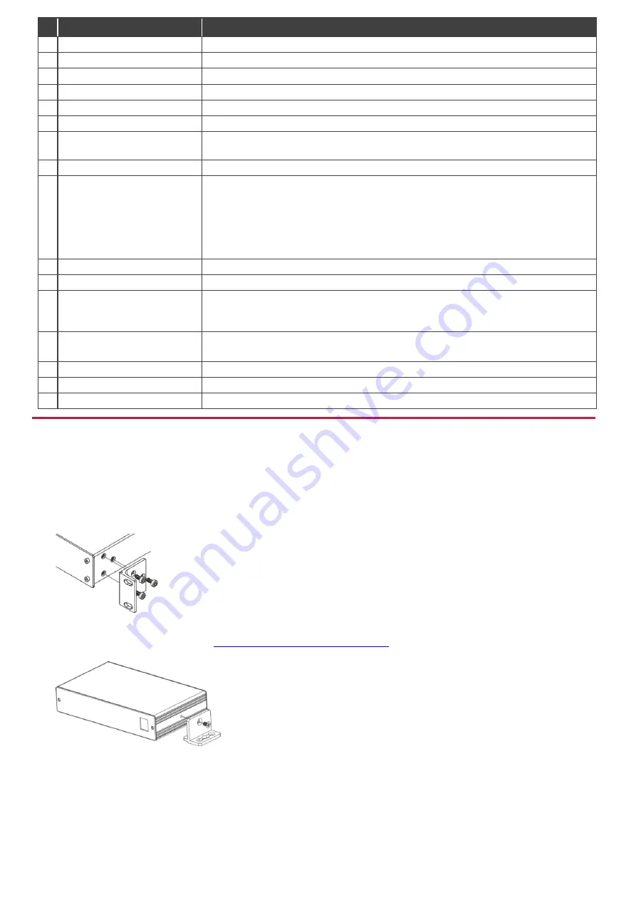
Step 3: Install VCO-1, VCO-5UHD, VCO-8, VCO-16
Install
VCO
devices using one of the following methods:
VCO-1,
VCO-5UHD,
VCO-8,
VCO-16
: Attach the rubber feet and place the unit on a
flat surface.
VCO-8
,
VCO-16
: Remove the three screws from each side of the unit, reinsert those
screws through the rack ears and mount on a 19" rack.
VCO-1
: Fasten a bracket (included) on each side of the unit and attach it to a flat
surface. For more information go to
www.kramerav.com/downloads/VCO-1
Mount the unit in a rack using an optional
RK-3T
rack adapter for
VCO-1
and
RK-1
rack adapter for
VCO-5UHD
.


