


45
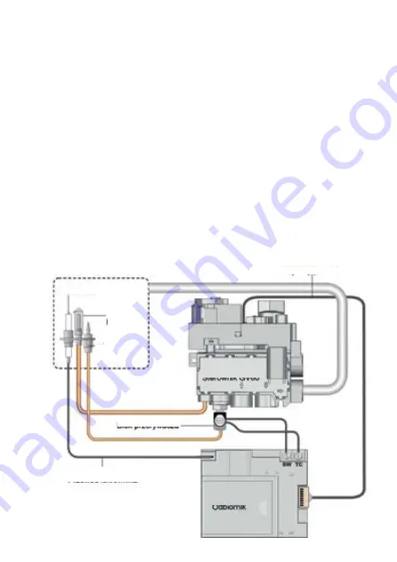
Magneto
Control
burnner
8 core cable
Interrupter block
Magneto wire
Receiver
GV60 controller
Installation of the control system
NOTE!!!
The device with its gas control system can be installed only with its factory settings. At this
stage, do not install the battery in the receiver. Earlier connecting to a power supply may cause
damage to the electronics system.
NOTE!!!
Individual gas control system components, connect according to the diagrams provided in this
manual.
The standard gas control system includes a MaxitrolMertik GV60 controller and a B6R-R8U receiver
from which an antenna enables operation of the device using a remote control. Remote control gas
components should be installed in the connection box. The connection box must be installed in an
accessible place for possible repair or replacement of individual components of the system. Exposure
of the electronic system to temperatures exceeding 60°C will result i n irreparable damage. Elements
of the control system should be installed in a place where the temperature does not exceed 25°C.
The maximum distance between the contr ol box and the gas stove is determined by the length of
the cables connecting the GV60 gas control with the electrode and thermocouple. Do not extend the
cables provided with the unit, as this may affect the control system malfunction.
Keep in mind not to put the ignition cable too close to the metal parts. Contact of the ignition cab-
le with the receiver housing can cause damage. Components of the system may not be exposed to
moisture, dust, and factors affecting the formation of corrosion. Freestanding STOVE AB can operate
only with the gas control system supplied with the unit. When replacing individual components of the
system, use only original parts available for purchase from the manufacturer. Plugs of individual wires
are chosen in such a way as to prevent incorrect connection of components.
Figure 6. The wiring diagram of the
system components for gas control
Summary of Contents for KOZA AB GAZ
Page 4: ...4 Rys 1 KOZA AB GAZ zasilana gazem Rys 2 Wymiary gazowego ogrzewacza pomieszcze KOZA AB GAZ...
Page 39: ...39 Rys 1 KOZA AB GAZ gas stove Rys 2 Dimensions Freestanding STOVE AB S EN...
Page 47: ...47 Figure 10 Removal of the doors Figure 9 Removal of the bottom cover...
Page 50: ...50 Fig 12 How to install a settler if required...
Page 72: ......
Page 74: ...74 Fig 1 KOZA AB GAZ gaz Fig 2 Dimensions du chauffage gaz KOZA AB GAZ...


