


46
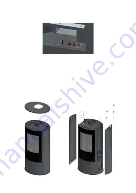
Figure. 8. Removal of the top plate and the side panels
Figure 7. The way of routing out and sealing the capillary cable, the magneto wire, the tube of the
main burner and the tube of the control burner
Passing individual wires through the casing of the gas stove, pay close attention to how they are
sealed. Sealing is achieved by means of special bushings and heat- resistant paper. Other elements
should be sealed with high-temperature silicone.
DISASSEMBLY OF THE DEVICE
In order to gain access to the individual components of the automatic gas control system used in the
AB GAZ heater, first remove the top cover and then unscrew the side wall screws. After loosening the
screws, lift the side panels (Fig. 8). Then remove the bottom cover. The bottom cover is fitted with four
M5 screws (Fig. 9).
In order to have access to the combustion chamber, main burner and control burner module, remove
the door by unscrewing the 8 M5 screws as shown in figure 10. Next, remove the inner glass by loose-
ning the pressure strips (16 M5 bolts). Removal of the inspection is possible by unscrewing 6 screws
Summary of Contents for KOZA AB GAZ
Page 4: ...4 Rys 1 KOZA AB GAZ zasilana gazem Rys 2 Wymiary gazowego ogrzewacza pomieszcze KOZA AB GAZ...
Page 39: ...39 Rys 1 KOZA AB GAZ gas stove Rys 2 Dimensions Freestanding STOVE AB S EN...
Page 47: ...47 Figure 10 Removal of the doors Figure 9 Removal of the bottom cover...
Page 50: ...50 Fig 12 How to install a settler if required...
Page 72: ......
Page 74: ...74 Fig 1 KOZA AB GAZ gaz Fig 2 Dimensions du chauffage gaz KOZA AB GAZ...


