49
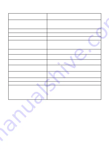
Technical specifications of the gas control system used in the freestanding stove
The gas control system used in the freestanding stove AB series meets the requirements for
appliances burning gaseous fuels in Directives 2009/142/EEC and DIN EN 298, DIN EN 126, DIN EN
13611. The system can be supplied with a gaseous fuel, second and third family according to PN-EN
437:2003+A1:2009 and PN-EN 613:2002+A1:2004.
First, make sure that the connected device is intended to be supplied with the type of gas contained
in the gas installation. All the necessary information about the required parameters of the gas can
be found on the nameplate of the stove. Before connecting the gas supply pipes, it is necessary to
purge them to remove metal filings and other contaminants from their interior. The automatic gas
control should be protected from moisture and dust. These factors may cause irreparable damage to
individual components. Gas supply pipes to the stove should be equipped with a ball valve of 1⁄2 inch
in diameter. Individual elements of gas installation cannot be sealed using a Teflon tape or PTFE tape
(Please use the sealing elements supplied with the unit). If the gas installation needs to be connected
to a settler, install it according to Fig. 12. The settler protects the controller from gas contaminants.
PRESSURE DROP/CAP ACITY
2009/142/EEC oraz DIN EN 298, DIN EN 126, DIN EN
13611
FUEL
Gaseous fuels of the first, second and third fami-
ly, according to PN-EN 437:2003+A1:2009 PN-EN
613:2002+A1:2004
PRESSURE DROP/CAP ACITY
2,5 mbar for 1,2 m
3
/h
ADJUSTMENT RANGE
Class C, according to EN 88
ADJUSTING THE REGULATOR
5 do 40 mbar (0,5 do 4 kPa)
MOUNTING POSITION
the module cannot be mounted with the breaker block
downwards. The control position can be adjusted in the
range from 0° to 90° relative to its home position
MAXIMUM PRESSURE OF INPUT GAS
50 mbar (5 kPa)
MAIN GAS INLET CONNECTION
Reducing nipple 1/2‘‘ na 3/8‘‘
CONTROL BURNER CONNECTION
M10x1 for a pipe of 6 mm
DISCHARGE OF THE MAIN GAS INLET
AND OUTLET
From the side or bottom
MAXIMUM TIGHTENING TORQUE
nlet and outlet connection
3
/
8
“: 35 Nm Control burner
connection:15 Nm
THERMOCOUPLE /BREAKER BLOCK
M10x1, M9x1, M8x1
IGNITION
Piezoelectric ignition
ALLOWABLE TEMPERATURE LIMIT
Controller: 0 °C to 80 °C
Receiver without batteries: 80 °C
Odbiornik z bateriami: 55 °C
Pilot: 60 °C
Przewód zapłonowy: 150 °C
Summary of Contents for KOZA AB GAZ
Page 4: ...4 Rys 1 KOZA AB GAZ zasilana gazem Rys 2 Wymiary gazowego ogrzewacza pomieszcze KOZA AB GAZ...
Page 39: ...39 Rys 1 KOZA AB GAZ gas stove Rys 2 Dimensions Freestanding STOVE AB S EN...
Page 47: ...47 Figure 10 Removal of the doors Figure 9 Removal of the bottom cover...
Page 50: ...50 Fig 12 How to install a settler if required...
Page 72: ......
Page 74: ...74 Fig 1 KOZA AB GAZ gaz Fig 2 Dimensions du chauffage gaz KOZA AB GAZ...