background image

INSTALATION SET COMPONENTS 

 REPLACEMENT PARTS 

Thoroughly inspect the appliance for shipping damage and immediately contact the dealer if any is 
found. 

Please make sure that the set components were not damaged during transport. The inspection should 
be carried out in the presence of the fitter. Before installing the fireplace insert, please learn all of the 
elements that came with the device. In the case of any damage or missing components, please contact 
our customer service. The user receives a set including: 


GV60M1 Metrik Maxitrol controller. 


B6R-R8U Metrik Maxitrol receiver. 


8 - symbol B6R-H8T5B remote control. 


Clamp connector 8 mm. 


Clamp connector 6 mm. 


One-piece clamp connector 6 mm. 


Screw plus 3/8’’ 

- 2 pcs. 


G60-ZUS09 interrupter block. 


Control burner block G30-ZP2M. 


Control burner nozzle - NG (number 27_2) LPG (designation 22) 


Seal under the control burner block. 


Thermocouple G30-ZPT1500A. 


Magneto wire. 


Cables connecting the interrupter block with the receiver. 


An 8-core cable connecting the gas controller with the receiver. 


Reducing nipple 1/2 ‚’ to 3/8 ‚’.


A set of decorative stones. 


Gas connection cables having a diameter of 6 and 8 mm. 


Distribution box. 


Power module G60-ZBE (Option). 


The cable connecting the power module with the receiver, 90º (Option).


Lighting control module and a G6R-BEAV2 fan (Option). 


The cable connecting the G6R-BEAV2 module with the receiver (Option). 


10-unit symbol B6R-H8TV14B remote control (Option). 


Steel frame holding the safety glass. 


4mm ceramic glass safety glass screen. 


Chamber 4mm ceramic glass. 


Holding bars. 


Top flashind flaps. 

Summary of Contents for LEO/100

Page 1: ...ot try to light any appliance Do not touch any electrical switch do not use any phone in your building Leave the building immediately Immediately call your gas supplier from a neighbor s phone Follow...

Page 2: ...3 2014 and GAS FIRED APPLIANCES FOR USE AT HIGH ALTITUDES CAN CGA 2 17 M91 This appliance may be installed in an aftermarket permanently located manufactured home USA only or mobile home where not pro...

Page 3: ...rmation to ensure safe installation and efficient dependable operation of your fireplace insert Please read these instructions in their entirety and make them available to anyone using or servicing th...

Page 4: ...HEARTH REQUIREMENTS FOR FLOOR PROTECTION 21 MANTELS 21 VENT INTRODUCTION 22 ELBOWS AND VENT RUNS CALCULATION 23 VENT TERMINATION HORIZONTAL SIDE WALL VENTING SYSTEM REQUIREMENTS 25 REPLACING PARTS CLE...

Page 5: ...spection and maintenance of the tightness of the device can be carried out only by qualified fitters technicians with licences appropriate for the given region INTRODUCTION The LEO 100 gas inserts are...

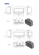
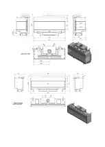
Page 6: ...DIMENSIONS...

Page 7: ......

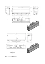
Page 8: ...Figure 1 Leo series dimmensions...

Page 9: ...2 Glass 3 Glass 1 Glass 2 Glass 3 Glass NG LP NG LP NG LP NG LP NG LP NG LP 77 21 78 50 77 98 78 98 78 34 82 15 73 97 75 41 75 06 75 29 73 63 74 57 CSA P 4 Fireplace Efficiency Safety barrier Ceramic...

Page 10: ...be installed in accordance with the Standard CAN CSA Z240 RV Recreational Vehicles in Canada or with ANSI A119 2 NFPA 501C Standard for Recreation Vehicles in the United States In case of any removal...

Page 11: ...ppliance if any part has been under water Immediately call a qualified service technician to inspect the appliance and to replace any part of the control system and any gas control which has been unde...

Page 12: ...tery replacement Always shut off the main gas supply to the appliance during inspection maintenance or cleaning Electrical Hazards Be aware of electrical wiring locations when cutting holes in walls a...

Page 13: ...ight 8 feet above grade directly in line with the exhaust vent terminal for the horizontally vented gas fueled heating appliance or equipment The sign shall read in print size no less than one half 1...

Page 14: ...connector 6 mm Screw plus 3 8 2 pcs G60 ZUS09 interrupter block Control burner block G30 ZP2M Control burner nozzle NG number 27_2 LPG designation 22 Seal under the control burner block Thermocouple G...

Page 15: ...ng again It is strictly forbidden to make any modifications in the design of the fireplace Gas control system components must not be exposed to moisture Do not operate the unit without inserting its g...

Page 16: ...2014 CSA 2 33 2014 and GAS FIRED APPLIANCES FOR USE AT HIGH ALTITUDES CAN CGA 2 17 M91 LOCATION YOUR GAS FIREPLACE Before connecting the device to a gas pipe and chimney carefully choose the location...

Page 17: ...inimum vent vertical and allowed horizontal lengths and number of bends must be considered during the location selection for your fireplace The appliance must be installed on a flat solid continuous s...

Page 18: ...CLEARANCE REQUIREMENTS Figure 2 Levelling foot and adjustable bracket to attach to the wall Figure 3 Minimum clearances of the LEO fireplace unit from the housing walls...

Page 19: ...ned to not disturb the aesthetic incorporation of the fireplace to its surrounding living space A technician should also service the fireplace controls and valves by going through the firebox This pro...

Page 20: ...e Optional Manufacturer may provide you a face tamplate to make it easier for you Contact your authorized dealer to ask for further information Figure 4 Scheme of the accessibility clearance for servi...

Page 21: ...extend for at least 39 inches of the front and both sides of the unit unless the floor and the walls are non combustible This appliance must be placed on noncombustible concrete floor The bottom air...

Page 22: ...bodily injury or loss of life Never modify any venting component or use any damaged venting product THE GAS APPLIANCE AND VENT SYSTEM MUST BE VENTED DIRECTLY TO THE OUTSIDE OF THE BUILDING AND NEVER...

Page 23: ...t Elbow 3 feet so the total length is 21 feet Note Total lenght of vent run may vary from 10 feet 3 feet V 3 feet H elbow to 39 feet 26 feet V 10 feet H elbow C If there are two eblows in the vent sys...

Page 24: ...DirectVent PRO installation scheme Your DuraVent DirectVent PRO system shall be screwed tightly with screws and high temperature resistan silicone as shown below Figure 7 DuraVent DirectVent PROI ins...

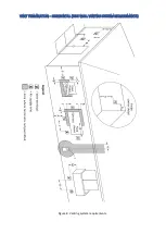
Page 25: ...VENT TERMINATION HORIZONTAL SIDE WALL VENTING SYSTEM REQUIREMENTS Figure 8 Venting system requirements...

Page 26: ...in 15 cm for appliances 10 000 Btu h 3 kW 9 in 23 cm for appliances 10 000 Btu h 3 kW and 50 000 Btu h 15 kW 12 in 30 cm for appliances 50 000 Btu h 15 kW K Clearance to a mechanical air supply inlet...

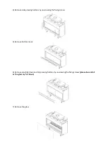
Page 27: ...ding to the following instructions PLEASE NOTE All the glasses has to mounted with instatling parts provided with the appliance only No substitutes to be used for installation 1 Unscrew the frame hold...

Page 28: ...pressing battens by unscrewing the fixing screws 5 Remove bottom mask 6 Remove carefully down and top pressing battens by unscrewing the fixing screws please be carefull as the glass my fall down 7 Re...

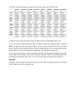
Page 29: ...TT MASK LEO 200 US BOTT MASK LEO 200 L US BOTT MASK LEO 200 P US BOTT MASK LEO 200 LP US BOTT MASK Top bottom battens LEO 100 US T B MASK LEO 100 L US T B MASK LEO 100 P US T B MASK LEO 100 LP US T B...

Page 30: ...EMENT Replacement of the glass or the flashing doors may require a gasket replacement also Please see the schemes below Ceramic glass and gaskets replacement scheme Top flashing doors gaskets and air...

Page 31: ...me Adjustment of gas pressure behind the regulator for the rated load Each time during the transition from each gas type to another set the apprpriate gas pressure behind the regulator Suitable pressu...

Page 32: ...suring point If despite to regulation you have failed to achieve the desired pressure check the pressure of supplied gas by connecting a manometer to the input pressure measuring point If the inlet pr...

Page 33: ...7 If you do not need to make any other adjustments turn of the fireplace disconnect the manometer and secure the connector of output pressure measuring point...

Page 34: ...d for installation at high altitudes in accordance with Canadian test standard CAN CGA 2 17 THE DERATING SHALL BE CARRIED OUT IN ACCORDANCE WITH THE REQUIREMENTS OF THE PROVINCIAL AUTHORITIES HAVING J...

Page 35: ...should be shipped fully assembled but during the installation your authorized installer might need to remove both glasses to finish gas connection into your fireplace At anytime when safety screein is...

Page 36: ...PROPER installation of decorative logs...

Page 37: ...ogs Please make sure that you will adhere to the above guidelines for proper fireplace operation Make sure that materials are spread out to maintain proper appearance and function of the flame Under n...

Page 38: ...n The elements should be arranged in such a way as not to obscure the flame control and the burner outlet openings otherwise it may cause incorrect operation of the fireplace The main burner of the fi...

Page 39: ...ng to a power supply may cause damage to the electronics system NOTE Individual gas control system components connect according to the diagrams provided in this manual The standard gas control system...

Page 40: ...Figure Mounting the gas controller with the receiver in the connection box Figure The wiring diagram of the system components for gas control...

Page 41: ...or replacement of the main burner with the right one WARNING The main burner module used in gas appliances in the LEO 200 series consists of two parts connected to the outlet of the GV60 controller by...

Page 42: ...ecting the gas control and the receiver away from hot parts of the fireplace The need to replace the batteries in the remote control is indicated by the indicator displayed in the upper right corner o...

Page 43: ...rom the user a system of automatic gas control will reduce the main burner flame to the minimum In the case of continuous operation without user intervention for five days after the last entry of sett...

Page 44: ...he remote control is synchronized with the receiver One long beep indicates that the elements of the system have not been properly paired Figure RESET button receiver INFORMATION To view the current v...

Page 45: ...CONTROL UNIT SETTING OF THE TEMPERATURE UNIT CHILD PROOF To change the temperature unit simultaneously press the buttons You can choose between Celsius and Fahrenheit degrees Choosing F will automatic...

Page 46: ...utton and the button 7 To confirm the setting simultaneously press and or wait Press the button until you hear two short beeps Starting the firing sequence is confirmed by the occurrence of a flashing...

Page 47: ...b to OFF and refer to the section Possible Problems and Solutions Standby or off mode Adjusting the height of the flame SETTING THE MINIMUM AND MAXIMUM HEIGHT OF THE FLAME Minimum height of flame To m...

Page 48: ...the button The display shows the HI symbol Enabling Settings 1 Press and hold until you see the icon The hours box will flash 2 Enter a value using the and buttons 3 To confirm press The minutes box w...

Page 49: ...s its maximum value and remains at a high level for a longer period of time If the room temperature is lower than the preset the flame height is reduced to a minimum for a long period of time One cycl...

Page 50: ...gs Press the button The display shows the icon and the 1 or 2 symbols and ON and OFF 1 Press the button or the button or the button to go to the manual mode 2 Press the button to go to the Thermostat...

Page 51: ...while you will see the ALL symbol Subsequently the hour will begin to flash 8 Set the hour using the and buttons 9 To confirm press The display shows the icon 1 ON then for a while you will see the AL...

Page 52: ...vibration Install only batteries of the same type and the same manufacturer Do not install new batteries with worn ones The remote control is powered by two AAA batteries The B6R R8U receiver and the...

Page 53: ...to the polarity markings on the receiver power module Replace the cover on the cover receiver supply module NOTE Replacing batteries in the receiver power supply module can only be done on a cool fir...

Page 54: ...he appliance Call authorized service agency if it is not The main burner flame should reach at least 1 3of the chamber height otherwise it may affect on the performance of you appliance and its work P...

Page 55: ...ot exposed to high temperatures Make sure that the switch box is not exposed to moisture Check that the connecting cords have no signs of corrosion 4 Combustion chamber inspection Make sure the contro...

Page 56: ...control can only be done by an authorized service technician There are many factors that could affect the gas insert malfunction To exclude a possible fault in the unit or the automatic gas control sy...

Page 57: ...he receiver If it is possible shorten the cable between the receiver and the electrode Add a grounding cable between the controller and the control burner No control flame Make sure that the gas shut...

Page 58: ...ystem The device cannot be turned off using the remote control Try turning off the burner using the switch on the gas control module setting it to O If there is no response replace the gas control mod...

Page 59: ...odes CSA B149 1 WARNING Improper installation adjustment alternation service or maintenance can cause injury or property damage Refer to the owner s information manual provided with this appliance For...

Page 60: ...y sheet lighting operating and shuting off instructions and elecrtrical diagrams LIMITED WARRANTY The Kratki pl Marek Bal company announces that the following warranty on the purchased device is only...

Page 61: ...the total amount of the product purchase confirmed by the original proof of purchase Indoor Gas Products 10 years 5 years 2 years 1 year Labor coverage years Combustion chamber body 3 Heat exchanger 3...

Page 62: ...the device or improper ventilation sealing the doors or windows supply of air necessary for combustion corrosive chemicals i e chlorine salt etc Any malfunction damage or irregularities related to the...

Page 63: ...regulations relating to civil liability under the Code of civil law should be limited to replacement repair or refund as described above The Kratki pl company shall in no event be liable under this wa...

Reviews: