63
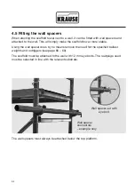
30°
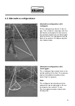
Alternative configuration with
outriggers
Fit the outriggers as shown in the im-
age. The connector couplings with the
half shells are designed to act as lock-
ing devices and have to be firmly tight
-
ened by hand. The outriggers must be
fitted at an approx. 30 degree angle to
the chassis beam.
Alternative configuration with
4 outriggers
The 4 outrigger feet always have to be
solidly resting on the floor. If necessary,
place unbreakable materials under-
neath them for support.
Note:
The outriggers have telescopic foot
plates that can be adjusted in 25 mm
increments for a total of 75 mm.
The foot plates must be locked with
locking pins.
4.4 Alternative configurations


