background image

-11- 

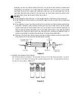
3.Installation Considerations


   When installing the water pipes, cannot install a drain stopper, in addition, for the water pipe bottom 

connector, the screw nut should have no wire teeth exposed. 

   If the inlet water pipe is 9mm, should ensure that the inlet water tube and connector have 30-40cm of 

straight piping to avoid burst pipe accidents caused by bending in the pipe. 

   If the power cord wiring needs to be longer, then according to the wiring requirements use a 

Φ8mm 

pinched tube to wrap around the connection, then on the  outside wrap around insulating electrical 

tape, do not place it on the floor, it should be suspended in the air or in another place away from the 

ground. 

  When installing, if you need to make a hole in the wall, you should first make sure that there are no 

electricity or water lines in the location you plan to drill. 


The  machine  must  be  connected  with  the  switch  with  reliable  grounding  line  ,  otherwise 

manufacturers are not responsible for safety accidents caused. 


The  switch  power  supply  must  switching  power  supply  must  put  in  ventilated  and  waterproof  place

  and  keep 

adequate distance with machine, in avoid of accidents caused by water input.


Adjustment Methods 


After confirming that the water route connections are correct, confirm that 

you have a power supply and/or water supply.    Then follow these steps 

to troubleshoot the machine: 


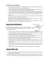
Diagram 11


1.  Open the tap water inlet valve as well as the water purifier inlet water ball valve, plug in the power 

source (See Diagram 11), close the storage tank ball valve, then automatically start  a 120 second 

flushing process, water will start to drain through the discharge outlet.                                                                                                                           

2.  Wait for the water purifier to operate stably (about 5-10 seconds), check each connection to make 

sure it is secure, see if there is any leakage from the membrane shell, filters, etc.                                                                                                                                                                               

3.  Close the pure water gooseneck faucet and storage tank ball valve, wait approximately 30 seconds, 

check whether or not the water purifier waste water has stopped. 

4.  Open  the  gooseneck  faucet,  observe  whether  pure  water  is  flowing  through  the  faucet,  if  no  pure 

water is flowing, check whether the tap water pressure is too low or whether the high pressure switch 

cannot be reset. 

5.  Wait until the machine is operating, close the inlet water ball valve, after a short time observe whether 

it has stopped operating, if it has stopped operating, check whether the low-voltage switch can be 

reset. 

6.  Wait some time to make sure everything is correct, then the water purifier can be used safely. 


Usage Methods


1.  The major components of this product are plastic, when using the product always observe the integrity of 

the water purifier to ensure safe use. 

2.  In order to prevent microbial contamination of membrane components during storage and transportation 

the reverse osmosis membrane element package contains a small amount of protective solution while the 

Summary of Contents for 800 COVER

Page 1: ...atment field It produces pure water that can be consumed directly so the water you drink is cleaner and also beneficial to your health Before you install and use this water purifier please be sure to...

Page 2: ...rations 7 2 Instructions for Proper Installation 8 3 Installation Notes 10 Adjustment Methods 11 Usage Methods 11 Maintenance and Upkeep 12 1 Filter Replacement Time 12 2 Computer Board show 12 3 Filt...

Page 3: ...o not put heavy objects on the water purifier If heavy objects are placed on the water purifier it may result in damage to the water purifier s dust cover or internal components which could lead to le...

Page 4: ...pipes and waste water ratio device are clogged it may lead to high TDS effluent the RO membrane may get blocked or the water purifier may not work Water purifier inlet water temperature should not exc...

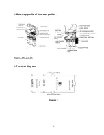
Page 5: ...5 1 Blown up profile of the water purifier Diagram 1 1Diagram 1 2 2 Electrical diagram Diagram 2...

Page 6: ...nts the above parameters may change but the product name plate shall stay the same TDS refers to the influent total dissolved solids 5 Water Purifier Main Parts Function Introduction Using the current...

Page 7: ...has reached the set pressure power supply is automatically cut off to stop the machine Inlet Water Solenoid Valve Connects or cuts off incoming water Operating pressure range is less than 0 6MPa Non...

Page 8: ...ctivity accessories required for installation Prior to installation turn off the water and or electricity 2 Instructions for Proper Installation Inlet water metal hose and 3 way inlet water joint inst...

Page 9: ...riate length of 6mm pipe into the water inlet connection put the 6mm pipe stopper into one end put on the 6mm nut screw to the bottom of the faucet see Diagram 7 If you want to fix the faucet to the w...

Page 10: ...er connection when installing correctly you only need a little force to put the reverse osmosis membrane into the membrane shell if you encounter too much resistance please do not force the reverse os...

Page 11: ...roubleshoot the machine Diagram 11 1 Open the tap water inlet valve as well as the water purifier inlet water ball valve plug in the power source See Diagram 11 close the storage tank ball valve then...

Page 12: ...estimated filter replacement cycle is based on average household water consumption and is suitable only for residential use do not install this machine in places that require large volumes of water I...

Page 13: ...set then press No 1 to reset 3 Filter Replacement Method Replacing the 1st and 3rd stage PP filters First close the inlet water ball valve using the filter cartridge wrench unscrew the 1st and 3rd sta...

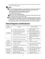
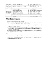
Page 14: ...ot start The power source is not connected Check the power source or the power source plug Low inlet water pressure or no water Check the inlet water pressure Low pressure switch failure cannot connec...

Page 15: ...or Notes The company reserves the right to change product design configuration and specifications without notice The company has the final explanation rights if this manual is unclear has mistakes or...

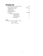
Page 16: ...d User Guide 1 copy Gooseneck faucet 1 Filter cartridge wrench 1 Membrane shell wrench 1 Accessory pack Consisting of 3 way inlet valve Inlet water ball valve Pipe stopper 6mm Faucet hanging piece Dra...

Reviews: