17
KRAUSMANN POWER TOOLS
U75020-00B
4
3
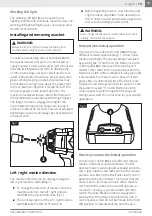
Working LED light
The working LED light
5
can be used in poor
lighting conditions to illuminate the work area. The
working LED light will light up as soon as you press
the ON / OFF switch
1
.
English |
EN
Forward (clockwise) operation
Reverse (counter clockwise) operation
Installing and removing a socket
To install a socket, align the socket holder
3
with
the socket receiver and press on until locked se-
curely in place. To remove a socket, pull the socket
off while twisting back and forth to dislodge (fig
2). When removing a socket or bits from the tool,
avoid contact with skin and use proper protective
gloves when grasping a socket. Accessories may
be hot after prolonged use. Apply the power tool
to the screw/nut only when it is switched off. The
torque depends on the impact duration. The
maximum achieved torque results from the sum
of all individual torques achieved through impact.
The longer the tool is engaged the higher the
accumulated torque value. Maximum torque is
achieved in about 45 seconds. The actual achieved
tightening torque should always be checked with a
torque wrench.
WARNING:
Always turn the tool off and remove the battery from
machine before doing any work on the machine.
The motor has an electronic clutch
4
with three
different forward speed settings: 1, 2, and 3 (low,
medium and high). The speed setting is adjusted
by pushing the ″S″ button on the Electronic clutch
control panel
4
on the base of the tool (fig 3). If
the ΟN / OFF switch
1
is momentarily pushed the
Electronic Clutch will be activated. If one green LED
is illuminated, the motor is set to Speed 1. If two
green LEDs are illuminated then the motor is set
to speed 2 and three green LEDs for speed 3. Push
the button marked ″S″ on the Electronic clutch
control panel to cycle through the three speed
settings and select the correct one for your specific
application.
The electronic clutch
4
has two different reverse
modes: Full Reverse and Auto Break. The Full
Reverse mode is automatically activated when the
Left / right rotation switch
2
is put into the reverse
position. No LEDs on the Electronic clutch control
panel should be illuminated. This means that the
clutch is set to full reverse mode. When the ΟN
/ OFF switch
1
is pushed the tool will operate in
reverse for as long as you hold down ΟN / OFF
switch. The Auto Break function is engaged by
pushing the ″B″ button on the Electronic clutch
control panel. A red LED will illuminate in the third
LED position to indicate that the Auto Break is
fig 2
fig 3
The rotation direction can be changed using the
left / right rotation switch
2
(fig 1).
Before beginning to work, check that the left
/ right rotation switch
2
is in the desired posi-
tion in order to avoid potential damage to the
tool or to the battery powered drill.
To change the direction of rotation, stop the
machine and turn the left / right rotation
switch
2
in the desired direction (fig 1).
T
he central position of the left / right rotation
switch
2
locks the ON / OFF switch
1
.
Left / right motion direction
WARNING:
Never change the direction of rotation when the chuck is
rotating. Wait until it has stopped.


