8
U87020-00B
KRAUSMANN POWER TOOLS
NOTE:
Make sure that the screw and nut are tight enough so that
the disc guard cannot be moved.
Τhe operation guard
must be fitted to the angle grinder at all times during use.
i
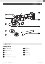
Attaching the auxiliary handle
Ensure the tool is switched off. Identify the two
threaded holes on each side of the grinder head.
Screw the auxiliary handle
5
firmly into one of
them (fig 2).
Installing and removing a disc
Turn the angle grinder on to its back and press the
spindle lock button and rotate the spindle until it
locks. Install the spacer on the axle. Place the disc
on the spacer. Screw the tension nut to the axle.
Press the spindle lock button
2
and tighten the
tension nut using the wrench
7
(fig 3)
. Release the
spindle lock button. To remove the disc, follow the
procedure in reversed order.
WARNING:
Before installing or removing a disc always remove the
battery from the tool.
CAUTION:
Do not use excessive force to clamp the disc. It could crack
it and cause failure during use.
Using the tool
Switching ON and OFF
To switch the tool on, slide the ON / OFF switch
1
towards the disc. For continuous operation, press
the front of the ON / OFF switch
1
to lock it.
To turn the tool off, slide the O
N / OFF switch
1
towards the rear part of the machine (fig 4).
Start the grinder and let it reach its full speed
before you begin working. While grinding, hold the
grinder at approximately 15° to 30º to the work
area. Do not exert side pressure on the disc.
Follow all the precautions in this manual and keep
a steady even pressure when you work. Remem-
ber that there is always the possibility that the disc
could fracture so do not force the tool.
W
hen you have finished, switch off and remove
the battery from the tool.
The operation guard
4
is held in place by a clamp
ring secured to the grinder head by a screw (fig
1). Loosen the fixing screw and rotate the guard
to the desired position, where it will deflect hot
sparks away from the operator. Then tighten the
fixing screw. To remove, follow the procedure in
reversed order.
Spindle lock button
WARNING:
The disc continues to turn for a few seconds even though
the switch is turned off. Keep your hands well away from
the moving disc.
Even if the battery cartridge is installed on the tool
with the ON / OFF switch
1
in the “ON” position,
the tool does not start. To start the tool, first slide
the ON / OFF switch toward the “OFF” position and
then slide it toward the “ON” position.
The tool features an electric brake with which
the engine stops working if the rotational speed
suddenly decreases or is under high pressure, to
provide greater protection and safety to the opera-
tor in case the disc gets stuck in the cutting area.
Press the spindle lock button
2
to prevent spindle
rotation when installing or removing accessories
(fig 4).
Accidental re-start preventive
function
Electric brake
CAUTION:
Never engage the spindle lock whilst the spindle is
rotating.
Using the dust screen
6
will increase the perfor-
mance and extend the life of the tool.
To attach the dust screen, snap the screen over the
tool’s handle.
T
o remove the dust screen, insert a flat screw
-
driver into the notch at the top of the dust screen
and pry away from the tool.
To clean the dust screen, tap against a hard sur-
face, or blow clean with compressed air.
Installing/Removing/Cleaning
the Dust Screen
English |
EN
Summary of Contents for U87020-00B
Page 2: ...2 U87020 00B KRAUSMANN POWER TOOLS 5 4 Fixing screw Hole Hole 6 2 2 1 fig 1 fig 2 fig 4 fig 3...
Page 11: ...11 KRAUSMANN POWER TOOLS U87020 00B ON OFF 1 2 3 1 4 9 8 7 6 2 5 5 2 3 8 9 4 7 1 6 GR GR...
Page 12: ...12 U87020 00B KRAUSMANN POWER TOOLS OFF 2 GR...
Page 13: ...13 KRAUSMANN POWER TOOLS U87020 00B ON OFF GR...
Page 15: ...15 KRAUSMANN POWER TOOLS U87020 00B 80 M X E 10 11 12 13 14 8 9 6 7 3 4 5 2 M GR...
Page 18: ...18 U87020 00B KRAUSMANN POWER TOOLS 6 ON ON OFF OFF ON 5 A 6 T T GR...
Page 20: ...20 U87020 00B KRAUSMANN POWER TOOLS U87020 00B www krausmann gr...

