background image

Krell Showcase Processor

53

System Configuration, 

continued    

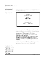
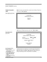
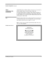
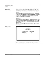
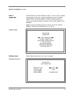
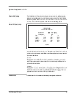
PLII Control Screen

SHOWCASE

-PLII CONTROL-

CENTER WIDTH         


0


DIMENSION                         3

After setting your selections, press the previous key once to return to
the 

CONFIGURE LEVELS 

screen.

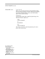
Use the 

PLII CONTROL

menu to adjust the signal for Dolby Pro Logic II

music mode, which derives a 5.0 signal from two-channel material.

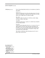
DIMENSION

You can adjust the sound field toward the front or rear loudspeakers,
to achieve a more suitable balance from all loudspeakers with certain
recordings. The adjustment range is 0 (maximum surround) to 6
(center). The default setting is 3 (neutral).

CENTER WIDTH

You can adjust how much of the center output signal is spread to the
left and right channel outputs. The adjustment range is from 0 (maxi-
mum center channel signal) to 7 (lowest signal; effectively mutes the
center channel).

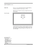
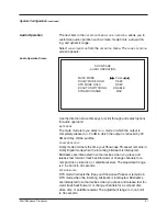
Select 

PLII CONTROL

from the 

CONFIGURE LEVELS

menu. The 

PLII CONTROL

screen appears: 

PLII Control

Summary of Contents for Showcase DVD

Page 1: ...Showcase Processor Surround Preamp Processor Instructions for Use Owner s Reference THE LEADER IN AUDIO ENGINEERING ...

Page 2: ...t available on CD LD and DVD soft ware which consequently cannot be decoded and played back inside most CD LD or DVD players For this reason when DTS encoded software is played back through the analog outputs of the CD LD or DVD play er excessive noise will be exhibited To avoid possible damage to the audio system proper precautions should be taken by the consumer if the analog outputs are connect...

Page 3: ...fiers and Sources 28 OVERVIEW SYSTEM CONFIGURATION AND NAVIGATION 30 Configuration Steps 30 Navigation Conventions 31 SYSTEM CONFIGURATION 32 Accessing the Main Menu 32 Step 1 Configure Loudspeakers 33 Step 2 Listening Room Setup 35 Step 3 Calibrate Volume 36 Step 4 Configure Devices 38 Step 5 Configure Level Adjustment 47 Step 6 Operation 55 SAVING AND RECALLING CUSTOMIZED SETTINGS AND RESTORING ...

Page 4: ...ase Processor Back Panel 17 FIGURE 5 The Showcase Processor Remote Control 21 TABLE 1 Video Signals and Video Formats Supported by the Showcase Processor 6 TABLE 2 Factory Default Video Inputs and Standards for the Showcase Processor North American Operation 39 TABLE 3 Factory Default Video Inputs and Standards for the Showcase Processor International Operation 39 TABLE 4 Factory Default Digital a...

Page 5: ... outputs user configurable input assignment and broadcast quality video circuitry The Showcase Processor is THX Ultra certified and features THX Surround EX Dolby Digital 5 1 Dolby Digital EX DTS ES 6 1 DTS NEO 6 and Dolby Pro Logic II processing in addition to nine propri etary Krell Music Surround modes This flexibility allows upgrades to software via Flash memory for future surround sound forma...

Page 6: ...single ended connec tions Single ended connections are not recommended for connec tions requiring long cable runs Off When the power switch on the back panel is placed in the down position and LEDs turn off the component is off Stand by Mode When the Showcase Processor is connected to AC power and the back panel power switch is in the up on position the red stand by LED illuminates This indicates ...

Page 7: ...parately transmits the luminance Y and color C components of the video signal using one wire Component Video A video signal that uses three wires to convey luminance Y red minus luminance R Y and blue minus luminance B Y signals Component video signals may be interlaced or progressive Progressive signals build screen content in one pass rather than the two passes required for standard interlaced v...

Page 8: ...the warranty registration card Carefully remove the Showcase Processor and accessories from the box Remove the foam end caps and protective plastic wrap from the component If any of these items are not included in the shipping box please contact your authorized Krell dealer distributor or Krell for assistance Save all packing materials If you must ship your Showcase Processor in the future repack ...

Page 9: ...ion the Showcase Processor requires at least three inches 7 cm of clearance between other connected components For installations inside cabinetry extra ventilation may be necessary The Showcase Processor has superb regulation and does not require a dedicated AC circuit Avoid connections through extension cords or multiple AC adapters High quality 15 amp grounded AC strips are acceptable High quali...

Page 10: ... video monitor The device must be active in order for both the OSD information and the menu to be visible North American Example Select the DVD device to an NTSC video monitor and use the com ponent video output to connect the Showcase Processor to your monitor International Example Select the VCR device to a PAL video monitor and use the S Video OSD output to connect the Showcase Processor to you...

Page 11: ...C o m p o s i t e 1 N T S C I n t e r l a c e d S V i d e o 1 N T S C I n t e r l a c e d C o m p o s i t e 2 N T S C I n t e r l a c e d Figure 1 Front Panel Input Device Selection Buttons and Associated Factory Default Video Signals and Video Formats for North American Operation of the Showcase Processor Note For CD TUNER AUX and GAME the factory video defaults are disabled and therefore a video...

Page 12: ...T S C I n t e r l a c e d S V i d e o 1 N T S C I n t e r l a c e d C o m p o n e n t 2 P A L I n t e r l a c e d C o m p o s i t e 2 P A L I n t e r l a c e d Figure 2 Front Panel Input Device Selection Buttons and Associated Factory Default Video Signals and Video Formats for International Operation of the Showcase Processor Note For CD TUNER AUX and GAME the factory video defaults are disabled ...

Page 13: ...with your con nected video monitor See Figure 1 for North American operation and Figure 2 for International operation This becomes the cur rently selected video signal output 4 Verify that the video monitor s video signal input corresponds to the Showcase Processor video signal output Press the menu key on the remote control to verify that the OSD is now viewable on the video monitor The system co...

Page 14: ...System on page 27 2 Configure the loudspeakers input devices and trims using the built in easy to follow system configuration menus Step by step instructions begin on page 32 System Configuration 3 Review the front panel back panel and remote control descrip tions for information on input and mode selections loudspeaker adjustment input and output connections for analog digital and video sources a...

Page 15: ... DVD Button 7 LD Button 8 SAT Button 9 VCR Button 10 TV Button Display 22 Front Panel Display Individual Channel Trim Buttons 23 Center Button 24 Surr Back Button 25 Sub Button 26 Balance Button Processor Function Buttons 27 Save Button 28 Direction or Level Buttons 29 Recall Button Figure 3 The Showcase Processor Front Panel S H O W C A S E PROCESSOR GAME VCR TV TAPE VCR2 DVD LD SAT CD TUNER AUX ...

Page 16: ...ds that the back panel power switch remain on at all times 4 Infrared Sensor The infrared sensor receives commands from the Showcase Processor remote control For proper remote control operation make sure the infrared sensor is not covered or obstructed 5 Infrared Emitter Emits the Showcase Processor remote operation code to a learning remote See Program Remote on page 61 The Showcase Processor is ...

Page 17: ...er device 13 Aux Button Use this button to select an auxiliary device such as phono tape or an additional DVD LD CD or VCR 14 Game Button Use this button to select a game 15 Tape VCR2 Button Use this button to playback pre recorded tapes You may also use this button to compare the output signal of an analog tape recorder to an audio source See Tape Input and Output on page 68 Front Panel Descripti...

Page 18: ...ncoming signals from a video or audio source The default mode for a signal is always stored in Mode 1 Use the Mode 1 button to select the default mode All modes that can be used for the same signal are automatically stored in Mode 2 Use the Mode 2 button to scroll through these other modes The last mode displayed in Mode 2 is the one selected Based on the source signal the Showcase Processor autom...

Page 19: ...essages for Showcase Processor operations including volume and balance level decoding mode and zone information In addition when a new device is selected the physical inputs are displayed The display turns off after 60 seconds of inactivity Note Individual Channel Trim Buttons Use the center surr back and sub buttons to change taste trims to make temporary speaker output adjustments of 10 dB These...

Page 20: ...sed in programming a learning remote See Saving and Recalling Customized Settings and Restoring the Factory Default System Settings on page 67 and Program Remote on page 61 28 Direction or Level Buttons Use these buttons to scroll through menu selections adjust the out put for the entire system and adjust balance and volume levels for the center loudspeaker surround back loudspeakers and subwoofer...

Page 21: ...omponent Video Inputs Back Panel Remote Control Connections 48 Comm Port RS 232 Remote Connector 49 RC 5 In 50 12 VDC In and Out Power Connections 51 Back Panel Power Switch 52 IEC Connector Figure 4 The Showcase Processor Back Panel 2 3 C SL 4 SBL 7 1 INPUTS L C SL SBL R SW SR SBR R L L R 1 2 3 L R ANALOG AUDIO INPUTS 4 5 6 7 IN OUT TAPE VCR IN OUT L R L R 1 2 3 4 DIGITAL AUDIO INPUTS R SW 1 3 2 ...

Page 22: ... Inputs The Showcase Processor is equipped with one set of balanced inputs with XLR connectors 33 Tape In Left and Right The Showcase Processor is equipped with one set of single ended tape inputs with RCA connectors 34 Tape Out Left and Right The Showcase Processor is equipped with one set of single ended tape outputs with RCA connectors 35 VCR In Left and Right The Showcase Processor is equipped...

Page 23: ...Showcase Processor is equipped with four S video inputs with DIN connectors 44 Composite Video Outputs The Showcase Processor is equipped with two composite video out puts with RCA connectors The main composite video output labeled OSD on back panel includes on screen display For dubbing purpos es the second composite video output does not include on screen display 45 Composite Video Inputs The Sh...

Page 24: ...trollers 50 12 VDC In and Out The 12 VDC output sends a 12 Volt power on off signal to other Krell components via a 12 V trigger cable as well as to other devices that incorporate 12 Volt power on off trigger input The Showcase Processor has four programmable 12 Volt outputs and one input When the Showcase Processor is in the operational mode and a trigger is enabled the 12 VDC Out provides 12 V o...

Page 25: ... 59 CD Key 60 Tuner Key 61 Aux Key 62 Aux 2 Key Game Key 63 VCR Key 64 Tape Key Processing Mode Keys 65 Stereo Key 66 M1 Key Mode 1 Key 67 M2 Key Mode 2 Key 68 Pro Logic II Key 69 Pre Key Preamp Pre Key Control Function Keys 70 Bal Key Balance Key 71 Cntr Key 72 Surr Back Key 73 Sub Key 74 Prev Key 75 Direction or Level Keys 76 Menu Key 77 Mute Key 78 Enter Key 79 THX Key Figure 5 The Showcase Pro...

Page 26: ...d the center of the remote while using your index fingernail or screwdriver to pull down gently on the slot to the right of the tab The battery compartment will slide out 3 Place the battery plus side up in the battery tray 4 Slide battery compartment back into the remote until you hear a click The remote control is ready for operation Do not use a knife or other sharp objects to open the battery ...

Page 27: ...FM tuner device 61 Aux Key Use this key to select the auxiliary device such as phono tape or an additional DVD LD CD or VCR 62 Aux 2 Key Game Key Use this key to select a game 63 VCR Key Use this key to select the VCR device 64 Tape Key Use this key to select the output from an analog tape recorder con nected to the tape inputs Showcase Processor remote control keys and their functions are describ...

Page 28: ...signals from a video or audio source The default mode for a signal is always stored in Mode 1 Use the Mode 1 key to select the default mode All other modes that can be used for the same signal are automatically stored in Mode 2 Use the Mode 2 key to scroll through these other modes The last mode dis played in Mode 2 is the one selected Based on the source signal the Showcase Processor automaticall...

Page 29: ...e Button 26 on page 16 Use the center surr back and sub keys to change taste trims to make temporary loudspeaker output adjustments of 10 dB These temporary changes revert to 0 dB when a new device is selected or the system is powered down For more information on taste trims and master program mable trims see Configure Level Adjustment on page 47 71 Cntr Key Use this key to select the center louds...

Page 30: ...round back loudspeakers and subwoofer Volume and balance levels are shown in the front panel display 23 76 Menu Key Use this key to access the system configuration on screen menus 77 Mute Key Use this key to mute the output of the Showcase Processor VOLUME MUTE appears in the front panel display 23 78 Enter Key Use this key to accept configuration menu selections accept an input device selection o...

Page 31: ...outputs 2 Neatly arrange and organize wiring to and from the Showcase Processor and all components Separate AC wires from audio cables to prevent hum or other unwanted noise from being intro duced into the system 3 For stereo analog input sources connect the right and left out puts of your source components to the inputs on the Showcase Processor The Showcase Processor is equipped with nine sets o...

Page 32: ...44 and one set of component video outputs One S video output one composite video output and the component video output include on screen display OSD For dub bing purposes only the S video and composite outputs labeled OSD display on screen information S video inputs can be seen only on S video outputs The same is true for composite and component video signals The Showcase Processor has balanced ou...

Page 33: ... to switch to the operational mode 5 Use either the front panel power button 1 or the remote con trol power pre key 54 to power on the Showcase Processor The blue power LED 2 on the front panel illuminates The Showcase Processor is now in the operational mode and ready to be configured Make sure that any source devices are off when you configure the Showcase Processor Connecting the Showcase Proce...

Page 34: ...ch loudspeaker in the system so that the Showcase Processor can synchronize the output to all speakers no matter where they are located in the room 3 CALIBRATE VOLUME The calibrate volume menu lets you set the volume to a reference evel to match the sensitivities of different loudspeakers and ampli fiers in your system 4 CONFIGURE DEVICES The configure devices menu lets you assign each device s in...

Page 35: ...uration menu screens 82 Menu Key Press this key once to enter the configuration menu The front panel display reads MENU MODE The MAIN MENU screen appears Press this key again to exit the configuration menu The Showcase Processor reverts to the operational mode 81 Direction or Level Keys Press these keys to scroll line by line through options on a menu screen After pressing enter 84 press the direc...

Page 36: ...ormation into the Showcase Processor through the interactive on screen menus These menus are structured to guide you through the setup process for each device or for your entire surround sound system System Configuration Press the menu key The front panel display reads MENU MODE The MAIN MENU screen appears ACCESSING THE MAIN MENU Main Menu Screen SHOWCASE MAIN MENU CONFIGURE SPEAKERS LISTENING RO...

Page 37: ...e crossover frequency Select CONFIGURE SPEAKERS on the MAIN MENU The SPEAKER SETUP screen appears If you have a 5 1 system select NO back speakers If you have a 6 1 system select 1 back speaker If you have a 7 1 system select 2 back speakers When 1 back speaker is selected the signal is present at the left back output STEP 1 CONFIGURE LOUDSPEAKERS Speaker Setup Screen SHOWCASE SPEAKER SETUP YES YE...

Page 38: ...etting is 80 Hz Choose the crossover frequency appropri ate for your loudspeakers The frequencies below the crossover frequency are sent to the subwoofer if a subwoofer is present other wise these low frequencies are sent to the full range loudspeakers in the system 5 1 SURR Select SURROUND BACK or BOTH to choose which loudspeakers in a 6 1 or 7 1 system receive surround information when playing a...

Page 39: ...OM SETUP screen the cursor is blinking at the LEFT loudspeaker Use the direction and enter keys to navigate the screen select loudspeakers and enter the correct distance 0 to 30 feet from the main listening position to the loudspeaker After all the distances are set press the previous key twice to return to the main menu Any speaker not configured in the SPEAKER SETUP menu displays N A not availab...

Page 40: ...inued Calibrate Room Setup Screen Auto Noise Sequence Auto Calibration Screen Note SHOWCASE CALIBRATE ROOM SETUP SELECT THE CALIBRATION METHOD AUTO NOISE SEQUENCE MANUAL NOISE SEQUENCE PROGRAM MATERIAL SHOWCASE AUTO CALIBRATION LEFT 0 DB L SURR 0 FT L BACK 0 FT CENTER 0 DB SUB 0 DB C BACK N A RIGHT 0 DB R SURR 0 DB R BACK 0 FT STEP 3 CALIBRATE VOLUME How To Navigate the Menu and Make a Selection 1...

Page 41: ... noise through the left loudspeaker While the individual channel on screen is blinking use the direction keys to adjust each loudspeaker s setting until the SPL meter reads 75 dB Press enter to set each selection then use the direction keys to move to the next loudspeaker Repeat this process for all loudspeakers Press the previous key twice to return to the main menu screen Any speaker not configu...

Page 42: ...cessor System Configuration continued Please read before continuing on to Step 4 STEP 4 CONFIGURE DEVICES The fourth option on the main menu screen CONFIGURE DEVICES allows you to assign video and audio inputs to source devices and configure triggers for devices in the system Select CONFIGURE DEVICES on the MAIN MENU The CONFIGURE DEVICES screen appears Configure Devices Screen SHOWCASE CONFIGURE ...

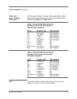
Page 43: ...1 Composite 1 S Video 1 S Video 2 Composite 2 Disabled Disabled Disabled Component 2 Composite 3 NTSC Interlaced NTSC Interlaced NTSC Interlaced NTSC Interlaced NTSC Interlaced N A N A N A NTSC Interlaced NTSC Interlaced DVD LD SAT VCR TV CD Tuner Aux 1 Aux 2 Game Tape Device Video Standard Assigned Input Component 1 Composite 1 S Video 1 S Video 2 Component 2 Composite 2 Disabled Disabled Compone...

Page 44: ...are INTERLACED or PROGRESSIVE HD depending upon your video source and monitor capabilities Use the direction and enter keys 75 to navigate the menu and set selections When all selections are entered press the previous key 74 once to return to the CONFIGURE DEVICES menu Assign Video Input Screen Assign Video Input SHOWCASE ASSIGN VIDEO INPUT DEVICE DVD ASSIGN INPUT COMPONENT 1 VIDEO STANDARD NTSC I...

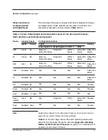
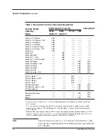
Page 45: ...uration Options Assigned Input Coax 1 Coax 2 Opt 1 Disabled Disabled Disabled Disabled Disabled Opt 2 Disabled DVD LD SAT VCR TV CD Tuner Aux 1 Aux 2 Game Tape Dolby Digital 5 1 DTS 5 1 PCM Analog Digital Analog Dolby Digital 2 0 Digital S1 S2 S3 VCR S4 B1 S5 7 1 Input S6 Tape Dolby D 5 1 Dolby D 5 1 Dolby D 5 1 N A N A N A N A N A Dolby D 5 1 N A Dolby D Dolby PLII Movie Dolby D Dolby PLII Movie ...

Page 46: ...ema DTS Neo 6 Cinema THX DTS Neo 6 Music Krell Music Surround Preamp Stereo YES YES YES YES YES YES YES YES YES YES YES 1 The DOLBY DIGITAL EX and DOLBY D 5 1 THX SURR EX operating modes are available only when your system has 6 or 7 channels 2 DTS 5 1 ONLY sets an input to receive only DTS 5 1 information When this mode is selected you are unable to select a default mode for PCM Dolby Digital 2 0...

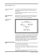
Page 47: ...DIO INPUT DEVICE AUTO MIGRATION DVD ON MIGRATION REC INPUT S1 ANALOG MODE PREAMP Select CONFIGURE AUDIO from the CONFIGURE DEVICES menu The ASSIGN AUDIO INPUTS screen appears Assign Analog Audio Inputs Assign Audio Inputs Screen SHOWCASE ASSIGN AUDIO INPUTS ANALOG DIGITAL How To Navigate the Menu and Make a Selection 1 Use the direction keys to scroll from line to line 2 Press enter to select a li...

Page 48: ...DISABLED to use the analog input and it must be set to DISABLED to use preamp mode PREVIOUS holds the last selected digital input The DOLBY DIGITAL EX DOLBY D 5 1 THX SURR EX DTS ES DISCRETE 6 1 and DTS EX MATRIX 6 1 operating modes are available only when your system has 6 or 7 channels When the device is configured press the previous key 74 twice to return to the CONFIGURE DEVICES menu System Co...

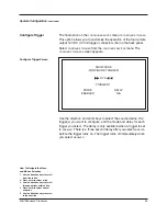
Page 49: ...h trigger you select The delay is only available when a trigger is set to ENABLED There is a three second delay after you select ENABLED before the trigger turns on The trigger turns off immediately when you select DISABLED System Configuration continued Configure Trigger SHOWCASE CONFIGURE TRIGGER MODE ENABLED DVD TRIGGER 1 DELAY N A Configure Trigger Screen How To Navigate the Menu and Make a Se...

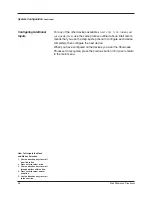
Page 50: ...configured all the devices you want the Showcase Processor to recognize press the previous button 74 twice to return to the main menu System Configuration continued Configuring Additional Inputs How To Navigate the Menu and Make a Selection 1 Use the direction keys to scroll from line to line 2 Press enter to select a line 3 Use the direction keys to scroll through options within a line 4 Press en...

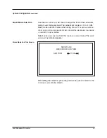
Page 51: ...ese inputs with out changes in volume levels The master volume control has a numerical range from 0 to 152 with 31 as the Dolby reference level The center loudspeaker surround loudspeakers and subwoofer volume trims have a range of 15 dB Select CONFIGURE LEVEL ADJUSTMENT from the main menu The CONFIG URE LEVELS screen appears System Configuration continued STEP 5 CONFIGURE LEVEL ADJUSTMENT SHOWCAS...

Page 52: ...and the trim level for each When you have made your selections press the previous key once to return to the CONFIG URE LEVELS screen System Configuration continued SHOWCASE DEVICE TRIM DVD 0 DB Device Trim Device Trim Screen How To Navigate the Menu and Make a Selection 1 Use the direction keys to scroll from line to line 2 Press enter to select a line 3 Use the direction keys to scroll through op...

Page 53: ...must be selected before the analog input trim option functions The following screen appears if an analog device is not selected SHOWCASE ANALOG INPUT TRIM PLEASE SELECT A DEVICE CONFIGURED WITH AN ANALOG INPUT PRESS PREV TO EXIT Please read before configuring analog input trim ...

Page 54: ...ut gain value off one step The optimal signal gain value will vary from source to source After selecting the anti clip and input gain options for your analog devices press the previous key 74 once to return to the CONFIGURE LEVELS menu System Configuration continued ANTI CLIP INPUT GAIN Use theANALOG INPUT TRIM menu to measure the level of an analog input source to the Showcase Processor Select AN...

Page 55: ... Trim Screen Music Mode Sub Trim Use the MUSIC MODE SUB TRIM menu to adjust the trim for the subwoofer during music mode playback The adjustment range is 10 to 10 dB Music mode sub trim is active when using the PARTY GENERALADMISSION FRONT ROW ON STAGE ENHANCED STEREO ORCHESTRA MEZZANINE FULL RANGE SUB and DTS NEO 6 modes Select MUSIC MODE SUB TRIM from the CONFIGURE LEVELS menu The MUSIC MODE SUB...

Page 56: ... left and right channels focused sound field Select DTS NEO 6 CONTROL from the configure levels menu The DTS CONTROL screen appears After setting the selection press the previous key once to return to the CONFIGURE LEVELS screen System Configuration continued DTS Control Screen DTS Control SHOWCASE DTS CONTROL CENTER GAIN 2 How To Navigate the Menu and Make a Selection 1 Use the direction keys to ...

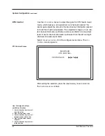
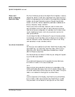
Page 57: ...ION You can adjust the sound field toward the front or rear loudspeakers to achieve a more suitable balance from all loudspeakers with certain recordings The adjustment range is 0 maximum surround to 6 center The default setting is 3 neutral CENTER WIDTH You can adjust how much of the center output signal is spread to the left and right channel outputs The adjustment range is from 0 maxi mum cente...

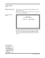
Page 58: ...um Volume Limit Screen Use the MAXIMUM VOLUME LIMIT menu to set the maximum volume for your system from 0 152 Select MAXIMUM VOLUME LIMIT from the CONFIGURE LEVELS menu The MAXI MUM VOLUME LIMIT screen appears Maximum Volume Limit How To Navigate the Menu and Make a Selection 1 Use the direction keys to scroll from line to line 2 Press enter to select a line 3 Use the direction keys to scroll thro...

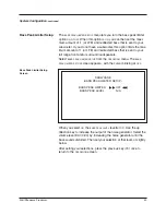
Page 59: ...er Select OPERATION from the MAIN MENU The OPERATION MENU screen appears with the cursur blinking at OSD OPERATION Press enter to access the OSD OPERATION screen System Configuration continued STEP 6 OPERATION Operation Screen OSD Operation Screen SHOWCASE OPERATION OSD OPERATION AUDIO OPERATION BASS PEAK LIMITER SETUP 7 1 INPUT SETUP PROGRAM REMOTE SYSTEM INFORMATION ROOM EQ SETUP SHOWCASE OSD OP...

Page 60: ...hoose the menu background either SOLID or TRANSPARENT The SOLID setting blanks out an active video signal and only displays menu information The TRANSPARENT setting overlays the menu screens on top of an active video signal allowing configuration changes while continuing to watch a video signal After setting your selections press the previous key 74 once to return to the OPERATION menu System Conf...

Page 61: ...mains in Dolby Digital mode when the incoming bitstream is interrupted Bitstreams are interrupted in some devices when you press and release fast forward track back forward or change channels for a compact disc video disc or satellite receiver The adjustment range is 0 no hold to 30 seconds DTS MODE HOLD DTS mode hold sets the time your Showcase Processor remains in DTS mode when the incoming bits...

Page 62: ... the dynamic range screen to adjust the dynamic range of the Showcase Processor Options are NORMAL 11 dB of compression MAX no compression NIGHT 22 dB of compression After setting your selections press the previous key 74 once to return to the OPERATION menu How To Navigate the Menu and Make a Selection 1 Use the direction keys to scroll from line to line 2 Press enter to select a line 3 Use the d...

Page 63: ...eturn to the OPERATION screen SHOWCASE BASS PEAK LIMITER SETUP OFF N A BASS PEAK LIMITER BASS PEAK LEVEL The BASS PEAK LIMITER SETUP menu lets you turn the bass peak limiter option ON or OFF When this option is ON you can then set the maxi mum amount of 1 or LFE and redirected bass that is sent to your subwoofer If you do not have a subwoofer this option limits the max imum amount of 1 or LFE and ...

Page 64: ... NO if it is not After setting your selections press the previous key 74 once to return to the OPERATION menu The 7 1 INPUT SETUP menu allows you to select the 7 1 inputs that are connected Select 7 1 INPUT SETUP from the OPERATION menu The 7 1 INPUT SETUP screen appears 7 1 Input Setup How To Navigate the Menu and Make a Selection 1 Use the direction keys to scroll from line to line 2 Press enter...

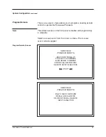
Page 65: ...EMOTE INPUT IS INACTIVE START The PROGRAM REMOTE menu allows you to program a learning remote control to operate the Showcase Processor The infrared sensor on the front panel is inactive until programming is complete Select PROGRAM REMOTE from the OPERATION menu The PROGRAM REMOTE screens appear SHOWCASE PROGRAM REMOTE ONLY U AND D SAVE AND RECALL ARE ALLOWED ON FRONT PANEL REMOTE INPUT IS INACTIV...

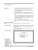
Page 66: ... save as many commands as desired 6 Press the recall button 29 on the front panel to exit the program mode System Information Screen System Information SHOWCASE SYSTEM INFORMATION AC LINE FREQUENCY SOFTWARE VERSION EEPROM VERSION EEPROM TYPE 60 HZ 0 6 2 2 The SYSTEM INFORMATION menu displays AC line frequency the version of software that your component is currently using and information about the ...

Page 67: ... on all seven channels of audio Alternatively each filter can be config ured separately for each individual channel TYPE Six filter types are available for each filter Notch Filter Peaking Filter High Shelf Filter Low Shelf Filter High Pass Filter HPF and Low Pass Filter LPF Each of the filter types available has a unique effect on frequency response The following three parameters for filters may ...

Page 68: ...the Showcase Processor is in the operational mode access the saved EQ configurations by pressing the right arrow key on the remote Use the up and down arrow remote keys to scan through the four memories and OFF Exit the main configuration menu by pressing the menu key 82 on the remote The Showcase Processor is now in operational mode Press the right arrow directional key followed by the up and dow...

Page 69: ...TUP screen appears with the cursor blinking at OFF Use the direction and enter keys on the Showcase Processor remote control to scroll through and select the following step by step options for audio operation MEMORY Navigate to one of the four memory locations and enter your selec tion When the Memory field is set to OFF the factory default all of the filters are disabled CHANNEL Navigate to CHANN...

Page 70: ...igurations you have just selected audi ble if you have a source device playing After selecting the appropriate loudspeaker configurationfor your sys tem press the previous key 74 twice to return to the main configu ration menu Exit the main configuration menu by pressing the menu key 82 on the remote The Showcase Processor is now in the operational mode How To Navigate the Menu and Make a Selectio...

Page 71: ... of the Showcase Processor Any settings that have been saved will be available through recalling system setup To replace all system settings with the factory default settings follow these steps 1 Press the front panel power button 1 to put your system into the operational mode 2 Simultaneously press the recall button 29 and the power button 1 The front panel displays PLEASE WAIT INITIALIZING Your ...

Page 72: ...her the front panel power button 1 or the remote control power pre key 54 to power on the Showcase Processor The blue power LED 2 on the front panel illuminates The Showcase Processor is now in the operational mode 5 To return to stand by press the front panel power button or power pre key again Krell recommends that the back panel power switch remain up on at all times The Showcase Processor has ...

Page 73: ...ff or mute the output This ensures that the next source played does not damage your system with a high output transient SIMULCAST When you are listening to or viewing different devices that have dif ferent trigger settings configured through the setup menus you can retain a trigger setting using the previous 74 key For example you have configured your Showcase Processor to turn on your TV monitor ...

Page 74: ...This is done using a matrix decoder that derives three surround channels from the two in the original record ing For best results Dolby Digital EX should be used with movie soundtracks recorded with Dolby Digital Surround EX All modes list ed under Dolby Digital EX including the default mode you have selected can be accessed using the M2 button or key DTS 5 1 Select a DTS 5 1 default mode using th...

Page 75: ...rpart to the original Pro Logic decoder It is the choice for the majority of Dolby Surround encoded material DOLBY PLII MUSIC The music mode is for use with unencoded stereo music recordings The music mode features dimension and center width controls see PLII Control on page 53 to enhance the music surround experi ence DOLBY PLII MATRIx The matrix mode is useful for monaural recordings DOLBY PRO L...
Page 76: ...eaker Position Time Synchronization lets you easily set up your system for an optimum listening position THX SURR EX THX Surround EX is a process that decodes a back surround signal from the left and right surround channels on specially encoded Dolby Digital DVD movie releases THX Surround EX uses all the process ing included in the THX operating mode see above Your system must include one or two ...

Page 77: ...sic The table below lists the modes and the speakers that operate within each mode Krell Music Surround Modes Operating Modes Active Loudspeakers GENERAL ADMISSION FRONT ROW ON STAGE ENHANCED STEREO ORCHESTRA MEZZANINE FULL RANGE SUB MONOPHONIC PARTY L R S RR L R S RR L R C S RR L R C S L R C S RR L R C S RR L R C S RR C S L R C S RR Table 6 Krell Music Surround Modes for the Showcase Processor ...

Page 78: ...States U S A is included in the warranty If you purchased your Krell product outside the U S A and wish to have it serviced at the factory all freight and associated charges to the factory are your respon sibility Krell will pay return freight to the U S A based freight forwarder of your choice Freight and other charges to ship the unit from the freight forwarder to you are also your responsibilit...

Page 79: ...e been made in advance Proof of purchase will be required for warranty validation at the time of hand delivery Use the original packaging to ensure the safe transit of the product to the factory dealer or distributor Krell may at its discretion return a product in new packaging and bill the owner for such packaging if the product received by Krell was boxed in nonstandard packaging or if the origi...

Page 80: ...a RCA connector ANALOG TAPE 2 pair single ended via RCA connectors ANALOG CHANNEL 8 balanced via XLR connectors one per channel 8 single ended via RCA connectors ANALOG TAPE 1 pair single ended via RCA connectors DIGITAL 1 coaxial via RCA connector 1 EIAJ optical via TosLink connectors VIDEO 2 S video via DIN connector 1 with OSD 2 composite via RCA connectors 1 with OSD 1 component via RCA connec...

Page 81: ...on Front Row On Stage Enhanced Stereo Orchestra Mezzanine Full Range Sub Monophonic Party 35 W INCHES 17 25w x 5 65h x 16 45d CENTIMETERS 43 82w x 14 35h x 41 78d SHIPPING 25 lb 11 3 kg UNIT ONLY 19 25 lb 8 75 kg All operational features functions specifications and policies are subject to change without notification POWER CONSUMPTION ...

Page 82: ...l Industries Inc 45 Connair Road Orange CT 06477 3650 USA TEL 203 799 9954 FAX 203 891 2028 E MAIL krell krellonline com WEBSITE http www krellonline com Showcase Processor Surround Preamp Processor v 02 3 ...

Reviews: