background image

Rev. Date: 3/8/17

Page 4

MODEL #4000-G-A

Electrical Safety

• The 

National Electric Code

(NEC) in the United States and many international electrical

codes require frame and external electrically conductive parts of this machine to be properly
connected to an approved earth ground.  Local electrical codes may also require proper
grounding of machine.  Consult with local electricians for grounding requirements in your area.

• Never handle any kind of electrical cord or device while standing in water, while barefoot or while

hands or feet are wet.  Dangerous electrical shock will result.

• Use a ground fault circuit interrupter (GFCI) in any damp or highly conductive area.  (metal decking

or steel work)

• Reference NFPA 79, 70E, or OSHA safe work practices when performing energized work procedures.

Safety/Caution

 Be Safe

 - Keep away from moving parts.

Be Safe 

- Make sure all guards and hopper extensions are in proper place 

before

 operating machine.

Guards and safety devices/switches should not be removed, modified or by-passed.
Hands should never pass between rotating parts.

Be Safe

 - Make sure remote control hand pendant switch is in 

off

 position 

before

 connecting the

power supply to the machine.

Be Safe

 - Make sure machine is properly grounded.  Protect all electrical supply cords from sharp

objects, moisture, and other potentially hazardous materials.  Keep power cords in good
repair.  Electrical service must be performed by a qualified electrician.

Be Safe

 - Disconnect power supply 

before

 inspecting or adjusting unit.

Be Safe 

- Consult a qualified technician to answer questions 

before

 attempting to operate, or injury

may result.

Be Safe 

-

Emergency Kill Switch - 

 In case of emergencies, always use red stop button located on

the front of Main Control Panel and on the side of the hopper.  It will stop all feeding and
agitation.

 Be Safe

 - Do not remove motors or lift hopper when unit is connected to power supply.

Be Safe

 - Do not operate machine alone.

Be Safe

 - Do not leave machine unattended and energized.

Be Safe

 - Turn machine off and disconnect electricity before clearing jam or attempting to remove

any object dropped in the hopper.

Be Safe

  - Keep hands, loose clothing, jewelry and hair away from agitators, gears, chains and other

moving parts.

Be Safe

 - Use proper lifting when moving insulation and loading machine.

Be Safe

 - Keep work area clear of debris.

Be Safe

  - Wear proper safety equipment, including protective gear, such as respirators, eye and ear

protection.

Be Safe

 - Violation of the Owner's Manual or safety precautions may void warranty.

Summary of Contents for 4000-G-A

Page 1: ......

Page 2: ... CAREFULLY BEFORE INSTALLING AND OPERATING YOUR MACHINE WARNING FOR ANY GAS OR DIESEL EQUIPMENT THAT IS NOT INSTALLED IN A TRUCK OR TRAILER BY KRENDL MACHINE WARRANTY WILL BE VOIDED IF NOT INSTALLED TO THE EXACT INSTRUCTIONS OF THIS MANUAL SEE INSTALLATION SECTION E MAIL ADDRESS IS krendl krendlmachine com WEB SITE IS www krendlmachine com ...

Page 3: ...RANTY 8 RETURNED GOODS PROCEDURE 9 SPECIFICATIONS 9 BASIC COMPONENTS 10 INSTALLATION 11 12 OPERATING INSTRUCTIONS 13 16 GENERAL MAINTENANCE 17 20 ELECTRICAL SYSTEM 21 23 LADDER DIAGRAM 24 TROUBLESHOOTING 25 26 SPARE PARTS LIST 26 PARTS LIST 27 34 GLOSSARY 35 SERVICE RECORD 36 Table of Contents ...

Page 4: ...fy the delivery trucking company immediately and file a claim for damages saving all packaging materials for inspection Our warranty covers manufacturer s defects only If Krendl Machine Company delivered or set up your machine and any parts are missing or damaged notify the authorized representative before they leave Krendl Machine Company Telephone 419 692 3060 1201 Spencerville Avenue Fax 419 69...

Page 5: ... and from any shipping pallet or skid to which it might be attached In addition completely remove all shipping materials from inside the machine Check that all parts are included as stated on the below ACCESSORIES INCLUDED 150 REMOTE CONTROL CORD MULTIMETER SPANNER WRENCH FOR BELT TENSIONERS 60 CHAIN MASTER LINK SECTION OF CHAIN FOR CHANGING SHREDDER DIRECTION EXHAUST SYSTEM 5 16 ALLEN WRENCH FOR ...

Page 6: ...chine or when compartment or electrical control doors need to be opened 8 If a malfunction occurs while running the machine turn it off immediately follow the directions under item 6 and correct the problem prior to restarting the machine 9 Keep body and all clothing away from rotating equipment Rotating shafts can be dangerous 10 Always wear proper safety equipment when operating the machine This...

Page 7: ... the machine Be Safe Make sure machine is properly grounded Protect all electrical supply cords from sharp objects moisture and other potentially hazardous materials Keep power cords in good repair Electrical service must be performed by a qualified electrician Be Safe Disconnect power supply before inspecting or adjusting unit Be Safe Consult a qualified technician to answer questions before atte...

Page 8: ... and pulleys are correctly aligned and tensioned Pieces of bag are not left in the machine as this can bind and stall your machine This machine should only be used with good quality insulations that are dry undamaged and that meet a certain industry specification or quality standards IF THERE ARE ANY QUESTIONS WITH YOUR KRENDL MACHINE DO NOT HESITATE TO CONTACT US AT 1 800 459 2069 Indicates which...

Page 9: ...sult in longer blower life and better performances Opens and closes the material feed gate which in turn controls the production Identifies position of material feed gate Made in the U S A KMC 01234 Part number for identification and tracking Indicateslocationofthefuel shut off valve Indicates that the Air Inlet must have unrestricted air flow at all times to prevent over heating of engine compart...

Page 10: ...s to be careful around electrical components This can cause serious injury or death Indicates that the engine requires fresh air Supplying the engine with fresh air will result in better performance and longer life During operation this machine is loud Wear hearing protection Failure to do this could result in hearing loss Identifies position of blower control Emergency stop button for machine Ind...

Page 11: ...on to preven tative maintenance etc 5 The product has been subjected to misuse negligence or accident or results of any application or use of the blowing equipment not in accordance with the Company recom mendations This limited warranty does not cover the free replacement of component parts that become inoperative due to wear and usage and need to be replaced on a regular basis including but not ...

Page 12: ...ndl cannot guarantee performance of the 4000 G A machine if hoses are undersized worn damaged or hoses other than those we recommend are used BEFORE YOU RUN THIS MACHINE PLEASE READ THE REST OF THIS MANUAL RETURNED GOODS PROCEDURE IF MACHINE WAS NOT PURCHASED DIRECTLY FROM KRENDL MACHINE COMPANY CON TACT YOUR SUPPLIER DISTRIBUTOR When returning products to Krendl for repair first obtain a return g...

Page 13: ...D Slidegate Meters the amount of insulation dropping into the airlock by controlling size of airlock opening E Speed Reducer Increases output power while decreasingspeedofagitator airlockdrivemotor F Agitator Conditions insulation in the hopper G Hopper Upperunitofmachineholdinginsulation H Motor Provides driving power for speed re ducer blower and agitator airlock system Illustration 2 I Main Con...

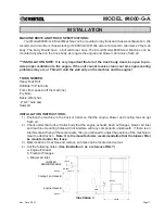
Page 14: ...r This will void the warranty on the machine and the engine TOOLS NEEDED Heavy Duty Drill Drill Bits 5 8 for bolts Fork Lift means to lift the machine Pry Bars Basic Wrenches 2 4 hole saw Sawzall INSTALLATION INSTRUCTIONS 1 Position the machine in the truck or trailer so that the engine blower and cooling fan can get fresh air 2 Check under the truck or trailer body that the engine exhaust fresh a...

Page 15: ...two 5 16 lag bolts 10 Attach the supplied 8 hose to the back guard and fresh air flanges Secure with hose clamps Do not cover the air inlet with any type of panel that may restrict airflow louvered panel expanded metal mesh screen filter ect It is imperative that the cooling fan has the necessary volume of air to keep the engine and other components from overheating WARNING Engines give off carbon...

Page 16: ...g 4 Make sure the control switch on the remote control cord is in the off position Now you may plug in the remote control cord 5 Start up engine and throttle up to 3200 RPM 6 Your machine is now ready for operation Note Agitator motor and blower should only be operated with steady or constant flow of electricity between 110 120 volts Note When using extension cords wire gauge size should not be le...

Page 17: ...ot run unless start button is pressed after Kill Switch is out See illustration 6 4 Select operating mode on 4 Position Selector Switch from one of the following options Remote Remote control hand pendant will control machine Off Machine will not run overrides remote hand pendant Blower Only the blower will run continuously manual control at machine Agitator Feed Blower Both the blower and the agi...

Page 18: ...cal Settings The controls of your machine contain the blower and slidegate controls to adjust your machine for each application and type of fiber See illustration 7 on page 16 Blower control air and slidegate material feed are adjusted according to TYPE OF MATERIAL Cellulose and fiberglass have different textures and densities that respond to machine settings HOSE Corrugations or roughness of inte...

Page 19: ... the blower valve while closing the slidegate proportionally This will increase the distance insulation can be blown through the hose while decreasing the blowing production rate lbs per hour blown See illustration 7 Shredder Assembly This unit is supplied with a shredder assembly airlock agitator speeds are preset at the factory No further sprocket setting speeds are needed as this system will ac...

Page 20: ...n and thereafter every 1000 hours GENERAL MAINTENANCE Your Krendl Model 4000 G A Machine is designed to be used with minimal maintenance for all its components The following is only a guide experience is the best guide for the right maintenance schedule for you SAFETYNOTE WHEN MAINTENANCE IS TO BE PERFORMED ON THE MACHINE ALWAYS 1 STOP THE ENGINE COMPLETELY 2 TURN THE IGNITION TO THE OFF POSITIONA...

Page 21: ...TE BLOWER OIL PNEULUBE Refer to blower manual GREASE MOBILITH AW 2 NLGI grade 2 ENGINE SAE SYNTHETIC MOTOR OIL OIL TYPE 5W 30 OR 10W 30 AIRLOCK REDUCER OIL KLUBERSYNTH UH1 6 460 Agitator Fittings 3 per side Shredder Fittings 2 per side Airlock Fittings 1 per side Bearing Grease Fittings Blower Fittings Jack Shaft Fittings Hopper Fittings 1 per side ...

Page 22: ...wer tabs of the seal down under the adjacent seal with a flat blade screwdriver Make sure all bolt holes are aligned while each side of seal is equally pressed against the end plates before tightening bolts Seal should be bent forwards for counter clockwise rotation See illustration 12 Illustration 10 Illustration 11 Base Plate Replacement 1 Remove damaged baseplate assembly from shaft using ratch...

Page 23: ...ctite general purpose thread locker to prevent gradual movement The set screws and key are also inserted with a medium grade Loctite If sprocket is difficult to remove it may be heated with a propane torch to loosen Caution Do not overheat sprocket or damage to bearing will result A pulley or bearing puller can then be used to remove the sprocket and key Replace new sprocket on shaft with key and ...

Page 24: ... D C 4000 32 R2 U S Illustration 13 ELECTRICAL DIAGRAM Periodically disconnect machine from power source and check all electrical connections and components for broken or loose wires loose screws or fasteners Machine Vibration can cause fasteners to loosen PANEL DOOR PANEL BOX ...

Page 25: ... 4000 32 R2 OS Overseas Illustration 14 ELECTRICAL DIAGRAM Periodically disconnect machine from power source and check all electrical connections and components for broken or loose wires loose screws or fasteners Machine Vibration can cause fasteners to loosen PANEL DOOR PANEL BOX ...

Page 26: ... Illustration 15 ELECTRICAL DIAGRAM Periodically disconnect machine from power source and check all electrical connections and compo nents for broken or loose wires loose screws or fasteners Machine Vibration can cause fasteners to loosen Orange Brown Black White Red Yellow Battery Battery ...

Page 27: ...Rev Date 3 8 17 Page24 MODEL 4000 G A LADDER DIAGRAM 12 VDC ...

Page 28: ...ild as required 4 Insufficient air clutch is operating A Check that the blower control valve isn t fully open Close or adjust the handle control as needed You should be able to get over 4 p s i of air on gauge See illustration 16 B Check that the blower relief valve is not stuck open See illustration 17 on page 26 C Check if blower air filter and intake hose is clogged D Check airstream and bypass...

Page 29: ...lease the material H If the airlock seals and or airlock components are worn or damaged replace all the parts as needed 5 No material flow clutch is operating A Check material level in main hopper B If the material slide gate is closed or adjusted in too far for material feed rate open the slidegate C Check the belts coming from the main drive shaft pulley to the reducer shaft drive pulley and blo...

Page 30: ...Rev Date 3 8 17 Page27 MODEL 4000 G A PARTS LIST 4000 G A Exploded Parts View Unidirectional Center Down ...

Page 31: ...Rev Date 3 8 17 Page28 MODEL 4000 G A 4000 G A Exploded Parts View ...

Page 32: ...Rev Date 3 8 17 Page29 MODEL 4000 G A 4000 G A Exploded Parts View ...

Page 33: ...k 6 Seal Airlock 6 Plate Bottom Airlock 6 Felt Seal 1 1 2 2 Bearing 4 Bolt 1 1 2 2 Sprocket 60 20T x 1 1 2 Key 3 8 x 3 8 x 1 1 4 Long Shredder Box Shredder Box Access Cover ShredderAgt Short 14Tine ShredderAgt Long 14Tine Seal FeltAirlock 1 Bore 4 Bearing 2 Bolt 1 4 Sprocket 60 11T x 1 2 Key 1 4 x 1 4 x 1 4 Slidegate Crankrod w Handle Bracket Handle Pin Cotter 1 8 x 1 N 3 8 16 Lock Nut Crimped Sup...

Page 34: ...Filterf 250300 2 R1 Blue Bushing Reducer 2 1 2 to 2 2 Adapter 2 Barb 2 Clamp Muffler 2 4 Pipe Exhaust 2 Flex Nipple Pipe 1 1 2 x 2 Long 4 Bracket Hose 2 Nipple Pipe 2 1 2 Close 2 Elbow 90 Degree 2 1 2 2 Nipple Pipe 2 1 2 5 Long Relief Valve 6 PSI Tee 2 1 2 2 Nipple Close 2 2 Tee w Pressure Relief Check Valve 2 1 2 Adapter Male Hose 3 Long Clamp Hose 3 4 Hose Radiator 3 12 Long Bracket Pulley Mount...

Page 35: ...ot Shown Muffler 4000 40 Oil Change Kit Bracket Mounting Muffler 4000 40 1 Oil ExhaustAdapter 4000 40 2 Oil Filter MufflerConnectorTube Pipe Exhaust 1 1 8 Flex 24 Long Pulley 3V450SDS Belt 3 3VX400 Taper Loc Bushing SDS 1 Oil Drain Air Inlet Manifold EngineManifold U Clamp 1 1 4 Muffler 3 Bracket Support Manifold Idler 3GR3V3 35 Guard Right Side Guard Motor 8 Cooling Fan Guard Loading Side Crankro...

Page 36: ... Cable Ties 48 2 Filter Fuel Fuel Shut Off Inline 1 4 Barb 1 4 x 3 16 Splicer Plastic Fuel Line 1 4 EPA 36 Long Fuel Line 1 4 EPA 30 Long Fuel Line 1 4 EPA 6 Long Clamp Spring Pinch 1 2 7 Gas Tank Tray Link Chain 1 2 50 NP Not Shown Sprocket 60 60T x 1 1 4 Bore Guard Chain Hopper Hopper Agitator Part 508 1 508 2 543 M 18 543 M 75 28 36 RM CT0048 28 57 BS 230 23001 RM OTH202 EPA RM OTH202 EPA RM OT...

Page 37: ...Switch Selector Green 12VDC Illuminated 49 13 543 O 02 Contactor Kill Switch not shown 49 14 543 M 38 Alarm for Pre Alarm System 24V 49 15 543 O 04 Switch Kill Illum 49 16 8075 1 Contactor Kill Switch not shown 49 17 KMCS 012 Decal SP Kill Switch not shown 49 18 4000 32 3 Socket 4 49 19 4000 32 7 Relay Timer Delay 49 20 4000 32 8 Relay Clip Timer 49 21 4000 32 2 Relay 12VDC Cube 3 49 22 4000 32 4 ...

Page 38: ...esive into an exposed WALL CAVITY SPRAY wall cavity to later be covered with drywall sheathing etc PSI Pounds of pressure per square inch The force exerted on a surface by air liquid High pressure blowers push the insulation through the hose Higher pressure provides less hose plugging and increased compaction in side wall PRODUCTION RATE Pounds of insulation blown per hour RPM Revolutions per minu...

Page 39: ...Rev Date 3 8 17 Page36 MODEL 4000 G A SERVICE RECORD DATE MAINTENANCE PERFORMED COMPONENTS REQUIRED ...

Page 40: ... MACHINE COMPANY 1201 SPENCERVILLE AVE DELPHOS OHIO 45833 TELEPHONE 419 692 3060 FAX 419 695 9301 E MAIL krendl krendlmachine com WEB SITE www krendlmachine com 55 YEARS OFAMERICAN INGENUITY Made in the U S A ...

Reviews: