background image

English

9

REMOVING TOOLS

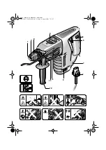
Slide the unlocking collar

 3

 to the rear and pull out the 

tool. 

ADJUSTING THE CHISEL

Set the rotation stop switch

 4

 to an intermediate posi-

tion. The chisel can now be turned by hand to the 
required working position. 
Return the rotation stop switch

 4

 to the initial position 

. The chisel latches automatically as soon as it is 

radially loaded by the working or chiselling process.

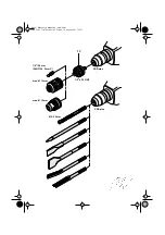
For drilling work in metal, wood and plastic with drills 
that have normal shafts, a drill chuck (13 mm max. 
chuck opening) is available. The drill chuck is 
mounted on the adapter (accessory) for screwdriver 
bits. All common drill chucks with 1/2" x 20 UNF inter-
nal threads (13 mm max. chuck opening) can be 
used. 

MOUNTING THE CHUCK 

Before any work on the machine itself, pull the 
mains plug!

Clean the threads of the drill chuck (accessory) and 
the adapter

 13

 (accessory). 

Screw the drill chuck onto the adapter and lock the 
adapter in the same manner as a drill in the tool 
holder. To tighten the drill chuck, set the rotation stop 
switch

 4

 temporarily to position 

Do not drill into hidden electrical 
lines or gas and water pipes. 
Check the area to be worked with a 
metal detector, for example, before 
starting.

For metal, use only flawless, sharpened drills; for 
stone and concrete, only masonry drills with hard 
metal inserts.
Always adapt the speed to the material to be worked 
and the diameter of the drill. For precision working 
with metal and wood, place the machine in a drill 
stand (accessory). 

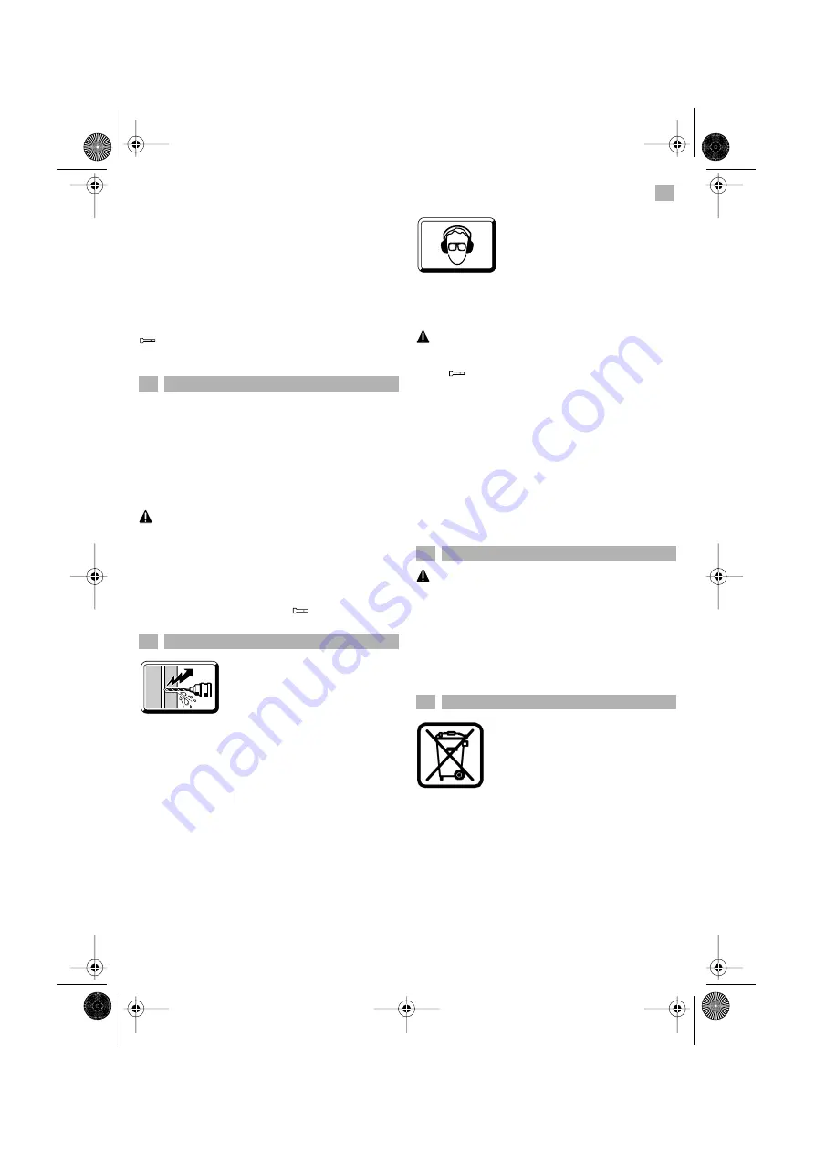
IMPACT DRILLING - CHISELING
Wear protective glasses and 
hearing protection.

Do not apply to much pressure. 
The performance is not increased 
in this manner.

The most effective method for chiselling is to break 
out only small pieces of material.

When chiselling, work only with protective glasses 
and the auxiliary handle

 12

. Check before starting 

to work if the rotation stop switch

 4

 is engaged in 

the  

position. 

DRILLING IN TILES 

Start drilling slowly on the tile. After the tile is drilled 
through, switch to impact drilling.

SCREWDRIVING 

Screwdriver bits can be inserted into the adapter

 13


(accessory). Commercially available bits with a hex-
agonal dimension of 6.3 mm or 1/4" (DIN 3126, 
Form C) can be used. 
The screwdriver bits are held in the adapter with a 
spring ring. Therefore, use only bits with a notch.

Before any work on the machine itself, pull the 
mains plug! 

Always keep the ventilation slots clean.
Wipe off the accessible plastic parts regularly with a 
cloth without cleaning agent.
After heavy use over a long period, the machine 
should be taken to a Kress service location for an 
inspection and thorough cleaning.

Recycle raw materials instead of dis-

-


The machine, accessories and packa- 

ging should be sorted for environ

-

mental 

friendly recycling.

Subject to change without notice

8

Drill Chuck (Accessory)

9

Practical Tips

10 Maintenance Measures

11 Environmental Protection

MBH 2002 - Titel.book  Seite 9  Freitag, 10. August 2001  7:52 07

recycling.

BMH 650

recycled paper 

These instructions are printed on 

The plastic components are labelled for categorised

manufactured without chlorine.

together with household waste


material!


Do not dispose of electric tools


posing as waste.

Summary of Contents for 0428 2645

Page 1: ...Kress Titelseite MBH 2002 OSW 08 01 Originalbedienungsanleitung 4 Original Instructions 7 Mode d emploi original 10 D GB F 36090_a 1103 MBH 2002 Titel book Seite 1 Freitag 10 August 2001 7 52 07 BMH 650 ...

Page 2: ...Kress Bildseite 1 MBH 2002 OSW 08 01 SDS plus SDS plus 1 2 x 20 UNF Ø 5 20 mm max Ø 13 mm max Ø 13 mm 1 4 6 3 mm DIN 3126 Form C 13 MBH 2002 Titel book Seite 2 Freitag 10 August 2001 7 52 07 ...

Page 3: ...Kress Bildseite 2 MBH 2002 OSW 08 01 MBH 2002 Titel book Seite 3 Freitag 10 August 2001 7 52 07 4 5 6 8 9 10 7 2 3 1 12 11 ...

Page 4: ...nopf für Ein Ausschalter 6 Ein Ausschalter Drehzahlsteuerung 7 Lüftungsschlitze 8 Arretierung Netzkabelmodul 9 Drehrichtungsumschalter 10 Umschalter Bohren Hammerbohren 11 Aufnahme für Tiefenanschlag 12 Zusatzgriff 13 Adapter für Schraub Bits Bohrfutter Abgebildetes oder beschriebenes Zubehör muss nicht zum Lieferumfang gehören Messwerte ermittelt entsprechend EN 60 745 Gehörschutz tragen 2 1 Sich...

Page 5: ...sam zu drehen mit zunehmenden Druck erhöht sich die Drehzahl DREHRICHTUNG UMSCHALTEN Betätigen Sie den Drehrichtungs umschalter 9 nur im Stillstand Greifen Sie den Drehrichtungsum schalter 9 beidseitig Rechtslauf Drehrichtungsumschalter 9 auf R stellen Linkslauf Drehrichtungsumschalter 9 auf L stellen Wichtig Drehrichtungsumschalter 9 jeweils bis zum Anschlag am Gehäuse durchdrü cken d h bis er sp...

Page 6: ...aues Arbeiten in Metall und Holz die Maschine in einen Bohrständer Zubehör setzen HAMMERBOHREN MEISSELN Schutzbrille und Gehörschutz tragen Üben Sie keinen zu starken Anpressdruck aus Die Leistung wird dadurch nicht erhöht Beim Meißeln wird die beste Wirkung erzielt wenn nur kleinere Materialstücke herausgebrochen wer den Beim Meißeln nur mit Schutzbrille und Zusatz griff 12 arbeiten Prüfen Sie vo...

Page 7: ...n off switch 6 On Off switch Speed control 7 Ventilation slots 8 Latch for mains cable module Measurement uncertainty K 1 5 m s 2 9 Rotational direction switch 10 Drilling Impact drilling selector 11 Holder for depth stop 12 Auxiliary handle 13 Adapter for screwdriver bits drill chuck Accessories illustrated or described are not always included as standard delivery items Measured values determined...

Page 8: ...sed pres sure the speed increases ROTATIONAL DIRECTION SWITCHING Operate the rotational direction switch 9 only when the machine is at a standstill Take hold of the rotational direction switch 9 on both sides Right rotation Set the rotational direction switch 9 to R Left rotation Set the rotational direction switch 9 to L Important Press the rotational direction switch 9 in each case to the stop o...

Page 9: ...ssory IMPACT DRILLING CHISELING Wear protective glasses and hearing protection Do not apply to much pressure The performance is not increased in this manner The most effective method for chiselling is to break out only small pieces of material When chiselling work only with protective glasses and the auxiliary handle 12 Check before starting to work if the rotation stop switch 4 is engaged in the ...

Page 10: ... position de travail sûre et stable et d utiliser ses deux mains pour maintenir fermement la machine en position 1 Fixation de l outil 2 Capuchon anti poussières 3 Bague de verrouillage 4 Stop de frappe 5 Cran d arrêt de l interrupteur Arrêt Marche 6 Interrupteur Arrêt Marche Molette de réglage de la vitesse 7 Ouïes de refroidissement 8 Dispositif de blocage du cordon d alimentation modulaire 9 Co...

Page 11: ...préa lablement Remarque Lorsqu un foret est monté sur la broche le fait d utiliser la rotation à gauche endommage le foret Lors de travaux avec des couronnes diaman tées et lors de travaux avec un agitateur mettre le mécanisme de frappe hors fonctionnement Pour les travaux de perçage en frappe utiliser exclusivement des forets carbure avec queue SDS Plus Il n est pas possible d utiliser des forets...

Page 12: ...us sières détérioré RETRAIT DE L OUTIL Repousser la bague de verrouillage 3 vers l arrière Extraire l outil hors de la fixation MISE EN PLACE D UN BURIN Mettre le commutateur de stop de frappe 4 dans une position intermédiaire Ceci fait l outil de burinage se laisse tourner sans difficulté dans la position de travail désirée Remettre ensuite le commutateur de stop de frappe 4 sur la position Le bu...

Page 13: ...lètement traversé le carreau de faïence VISSAGE L adaptateur 13 accessoire permet d utiliser les embouts de tournevis Il est compatible avec les embouts de tournevis du commerce dotés d une queue six pans de 6 3 mm 1 4 DIN 3126 profil C Les embouts de tournevis sont maintenus dans l adaptateur par un ressort Il convient donc de ne tra vailler qu avec des embouts dotés d une rainure laté rale Toujo...

Page 14: ...e CE Technical file at see TF CE Déclaration de conformité Nous déclarons sous notre propre responsabi lite que ce produit est en conformité avec les normes ou documents normalisés voir ce CE Dossier technique auprès de voirce TF DE EN FR EN 60745 1 EN 60745 2 6 EN 55014 1 EN 55014 2 EN 61000 3 2 EN 61000 3 3 2006 42 EG 2004 108 EG KRESS elektrik GmbH Co KG Postfach 166 D 72403 Bisingen Bisingen i...

Page 15: ... the guarantee 4 The guarantee may only be enforced when defects are reported without undue delay including shipping damage Guarantee im plementation does not extend the guarantee period 5 If the tool is defective please complete the guarantee card and re turn the unit guarantee card and a brief description of the problem to the responsible service location Please enclose your sales re ceipt 6 The...

Page 16: ...KRESS elektrik GmbH Co KG Postfach 166 D 72403 Bisingen Telefon 49 0 7476 87 0 Telefax 49 0 7476 87 342 Titelrueckseite_BH_sw fm Seite 56 Freitag 1 August 2008 8 51 08 ...

Reviews: