background image

English

7

Application

The pneumatic drill hammer is universally usable for 
hammer drilling and drilling as well as for screwdriving 
in wood, metal and plastic.

This pneumatic drill hammer is not suited for 
chiselling work (also not with pointed chisels).

Before putting the machine into operation, read 
through these operating instructions completely and 
observe the safety instructions contained therein as 
well as those in the enclosed booklet on general 
safety instructions for electro-tools.

If the mains cable is damaged while working, pull 
the mains plug immediately.

Never work with a damaged mains cable.

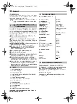
Wear protective glasses, hearing protection, pro-
tective gloves and sturdy shoes.

Do not work with materials containing asbestos.

Do not carry the machine by the cable.

The mains receptacles in the working area must be 
protected by a residual current circuit breaker (RC).

For the attachment of identification markings on the 
machine, do not drill into the housing. The protec-
tive insulation would be shorted. Use stickers.

When the drill unexpectedly jams, the machine 
kicks back. Therefore, always take a secure stance 
and hold the machine firmly with both hands.
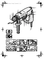
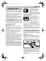
 1 Tool holder
 2 Dust protection cap
 3 Unlocking collar
 4 Clamping screw for auxiliary handle/depth stop
 5 Ventilation slots
 6 Rotational direction switch
 7 Locking button for on/off switch
 8 On/Off switchr
 9 Ventilation slots

 10 Drilling/Impact drilling selector
 11 Depth stop
 12 Auxiliary handle
 13 Adapter for screwdriver bits/drill chuck

Accessories illustrated or described are not always 
included as standard delivery items.

1

Safety Instructions and 
Accident Prevention

2

Illustration

3

Technical Data

Pneumatic Drill Hammer

Input power

5

5

0 Watt

Output power

2

7

0 Watt

Half-wave control


No-load speed

0-

100

0 RPM

Speed under load

0-7

5

0 RPM

No-load impact rate

max. 4

95

0 RPM

Load hammer blows

max. approx. 4

1

00 RPM

Impact energie

max. 2.0 J

Right/Left rotation


Clamping collar dia.

43 mm Euro standard

Tool holder

SDS-Plus

Drill dia., max.
Steel

13 mm

Light metal

16 mm

Wood

30 mm

Hammer drilling in 
conctrete

20 mm

Recommended hammer 
drilling range

5-14 mm

Screw dia., max.
Wood

6 mm

Sheet metal

6.3 mm

Corner measure

33 mm

Weight

2.175 kg

Protection class

II/


4

Noise/vibration information

PH 500 - GB  Seite 7  Dienstag, 18. September 2001  11:20 11

Wear hearing protection.


   Exposure to noise  

can cause hearing loss.


Use the auxiliary handles supplied with the  

machine. 

 Loss of control can cause personal  

injury.

Measured values determined according to 

EN 60 745.
Typically the A-weighted noise levels of the machine

are: sound pressure level 94 dB (A); sound power level
105 dB (A). Measurement uncertainty
K = 3 dB.

Wear hearing protection!

The typically weighted acceleration is 8,1 m/s

²

.

Summary of Contents for HM 550

Page 1: ...KRESS OSW 09 01 Titelseite PH 500 HM 550 I GB F D 4 7 10 13 Bedienungsanleitung Operating Instructions Mode d emploi Manuale di servizio 36149 0509HD ...

Page 2: ...KRESS OSW 09 01 Zubehörseite PH 500 SDS plus ø 5 20 mm 1 2 x 20 UNF 1 4 6 3 mm DIN 3126 Form C max ø 13 mm SDS plus max ø 13 mm 13 ...

Page 3: ...1 2 3 4 5 6 7 8 9 10 11 12 PH 500 Buch Seite 3 Montag 17 September 2001 11 54 11 ...

Page 4: ...hlag 5 Lüftungsschlitze 6 Drehrichtungsumschalter 7 Feststellknopf für Ein Ausschalter 8 Ein Ausschalter 9 Lüftungsschlitze 10 Umschalter Bohren Hammerbohren 11 Tiefenanschlag 12 Zusatzgriff 13 Adapter für Schraub Bits Bohrfutter Abgebildetes oder beschriebenes Zubehör muß nicht zum Lieferumfang gehören 1 Sicherheitshinweise und Unfallschutz 2 Bild 3 Technische Daten Pneumatik Bohrhammer Aufnahmel...

Page 5: ...chen Bohrfutters unter Ein satz des pneumatischen Hammerwerkes ist nicht möglich DREHRICHTUNG UMSCHALTEN Betätigen Sie den Drehrichtungs umschalter 6 nur im Stillstand Greifen Sie den Drehrichtungsum schalter 6 beidseitig Rechtslauf Drehrichtungsumschalter 6 auf R stellen Linkslauf Drehrichtungsumschalter 6 auf L stellen Wichtig Drehrichtungsumschalter 6 jeweils bis zum Anschlag am Gehäuse durchdr...

Page 6: ... mit Schutzbrille Gehör schutz und Zusatzgriff 12 arbeiten Prüfen Sie vor der Inbetriebnahme ob der Umschalter 10 in Stel lung eingerastet ist IN FLIESEN BOHREN Eine Fliese langsam anbohren Erst wenn die Fliese durchbohrt ist auf Hammerbohren umstellen SCHRAUBEN Der Adapter 13 Zubehör kann Schraub Bits aufneh men Es können handelsübliche Bits eingesetzt werden mit dem Sechskantmaß 6 3 mm bzw 1 4 D...

Page 7: ...p 5 Ventilation slots 6 Rotational direction switch 7 Locking button for on off switch 8 On Off switchr 9 Ventilation slots 10 Drilling Impact drilling selector 11 Depth stop 12 Auxiliary handle 13 Adapter for screwdriver bits drill chuck Accessories illustrated or described are not always included as standard delivery items 1 Safety Instructions and Accident Prevention 2 Illustration 3 Technical ...

Page 8: ...junction with the pneumatic impact mech anism is not possible Operate the rotational direction switch 6 only when the machine is at a standstill Take hold of the rotational direction switch 6 on both sides Right rotation Set the rotational direction switch 6 to R Left rotation Set the rotational direction switch 6 to L Important Press the rotational direction switch 6 in each case to the stop on t...

Page 9: ...han dle 12 Check before putting into operation if the shift knob 10 is latched in the position DRILLING IN TILES Start drilling slowly on the tile After the tile is drilled through switch to impact drilling SCREWDRIVING Screwdriver bits can be inserted into the adapter 13 accessory Commercially available bits with a hex agonal dimension of 6 3 mm or 1 4 DIN 3126 Form C can be used The screwdriver ...

Page 10: ... supplémentaire butée de profondeur 5 Ouïes de refroidissement 6 Commutateur du sens de rotation 7 Cran d arrêt de l interrupteur Arrêt Marche 8 Interrupteur Arrêt Marche 9 Ouïes de refroidissement 10 Commutateur perçage simple avec percussion 11 Butée de profondeur 12 Poignée supplémentaire 13 Adaptateur pour mandrins et embouts de tournevis Les accessoires reproduits et décrits dans la notice d ...

Page 11: ... commerce avec l adaptateur 13 et le mandrin de perçage habituel en travaillant avec le mécanisme de frappe pneumatique COMMUTATION DU SENS DE ROTATION Le commutateur de sens de rotation 6 ne doit être actionné que lorsque la machine est à l arrêt complet Saisir le commutateur de sens de rotation 6 Rotation à droite mettre le commutateur de sens de rotation 6 sur la position R Rotation à gauche me...

Page 12: ...la machine Lors du perçage en frappe ne travailler qu avec des lunettes de protection une protection acoustique et la poignée supplémentaire 12 Avant la mise en service contrôler si le commutateur 10 est bien encliqueté dans la position PERÇAGE DANS DU CARRELAGE Le perçage d un carreau de faïence doit s effectuer à petite vitesse N activer le mécanisme de frappe qu après avoir complètement travers...

Page 13: ...versibilità 7 Pulsante di bloccaggio per interruttore di inserimento disinserimento 8 Interruttore di inserimento disinserimento 9 Feritoia di ventilazione 10 Selettore Foratura Foratura a martello 11 Battuta profondità 12 Impugnatura supplementare 13 Adattatore per bit cacciaviti mandrino portapunta Accessori illustrati o descritti non fanno necessaria mente parte del volume di consegna 1 Indicaz...

Page 14: ...co ed adattatore 13 né è possibile utilizzare un comune mandrino portapunta in caso di impiego del martello pneumatico CONTROLLO DI VELOCITÀ Con l interruttore acceso spento 8 si possono selezionare due livelli di velocità Per iniziare a perforare premere leggermente l interruttore acceso spento 8 livello di perforazione iniziale per avere la massima potenza di perforazione premere del tutto l int...

Page 15: ...one cuffie di prote zione e l impugnatura supplementare 12 Prima di mettere in esercizio la macchina controllare se il selet tore 10 si trova nella posizione FORARE LE PIASTRELLE Preforare delicatamente la piastrella ed inserire la fora tura a martello solo dopo aver perforato completamente la piastrella AVVITARE L adattatore 13 accessorio può alloggiare bit cacciaviti Possono essere utilizzati bi...

Page 16: ...745 2 6 EN 55014 1 EN55014 2 EN61000 3 2 EN61000 3 3 89 336 EWG 98 37 EG KRESS elektrik GmbH Co KG D 72406 Bisingen Bisingen im September 2005 Klemens Müller Leitung Produktoptimierung Manager Current Product ...

Page 17: ... ed 9 The provisions defined in Items 7 and 8 only apply to the Federal Republic of Germany GB Guarantee 1 Dieses Elektrowerkzeug wurde mit hoher Präzision gefertigt und unterliegt strengen werkseitigen Qualitätskontrollen 2 Daher garantieren wir die kostenlose Beseitigung von Fabrikations oder Materialfehlern die innerhalb von 24 Monaten ab Verkaufsda tum an den Endverbraucher auftreten Wir behal...

Page 18: ...lefax 46 0 42 16 16 66 E mail mail abnovum se Norge Ifö Electric AS P O B 336 Alnabru Brobekkveien 115 B N 0614 Oslo Phone 47 23 37 81 10 Talefax 47 23 37 81 20 E mail info ifoelectric no Hellas D Nikolaou Co Ltd Leonidoy 6 GR 17343 Athens Phone 30 1 975 37 57 Telefax 30 1 973 74 23 E mail gnikolaou yahoo com Espana Apolo fijaciones y herramientas s l Garrotxa Naves 10 22 Polig Ind Pla de la Brugu...

Reviews: