


8
English
Before any work on the machine itself, pull the
mains plug!
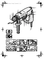
Operate the machine only with the auxiliary han-
dle 12. Place the auxiliary handle on the clamping
collar and tighten with the clamping screw.
Damaged mains cables must not be used. They must
be replaced without delay by an authorised servicing
agent (heavy rubber sheathed code designation
H 07 RN-F).
Check before putting into operation that the mains
voltage agrees with the voltage specified on the
nameplate of the machine.
SWITCHING ON/OFF
Press or release the on/off switch 8.
The on/off switch can be locked on with the locking
button 7. To release, briefly press and release the on/
off switch 8.
DRILLING - IMPACT DRILLING
For drilling, place the selector 10 in the
position.
For impact drilling, set to
.
The switch-over can best be performed at a standstill.
Only after the on/off switch 8 is actuated and the
machine starts does the gear box shift to the selected
mode.
Note: Left rotation when impact drilling damages the
drill. Switch off the impact mechanism for diamond
crown drilling or for mixing work.
When hammer drilling, use exclusively drills with
hard metal inserts and SDS-Plus shafts. The use of
commercially available masonry drills with cylindrical
shafts by means of the adapter 13 and the normal drill
chuck in conjunction with the pneumatic impact mech-
anism is not possible.
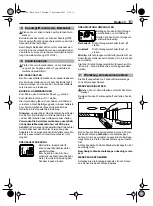
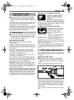
Operate the rotational direction
switch 6 only when the machine is
at a standstill!
Take hold of the rotational direction
switch 6 on both sides.
Right rotation: Set the rotational direction switch 6
to “R”.
Left rotation:
Set the rotational direction switch 6
to “L”.
Important: Press the rotational direction switch 6 in
each case to the stop on the housing, i. e. until it can
be felt to engage.
If the rotational direction switch 6 is set between the
positions “R” and “L”, the machine cannot be switched
on.
The tool holder 1 clamps the drilling tools without
using a tool key.
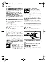
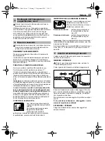
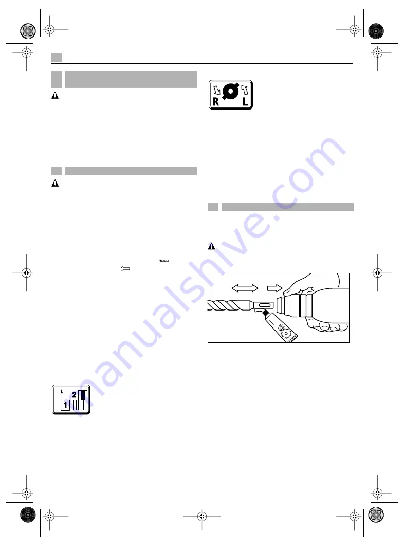
INSERTING TOOLS
Before any work on the machine itself, pull the
mains plug!
Clean and lightly grease the tool shaft.
Pull back the unlocking collar 3. Insert the tool while
turning into the tool holder until it latches. Release the
unlocking collar. Check whether the tool is firmly
seated.
Take care that the dust protection cap 2 is not dam-
aged.
Replace damaged dust protection caps!
REMOVING TOOLS
Slide the unlocking collar 3 to the rear and pull out the
tool.
5
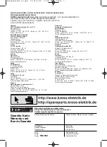
Mounting the Auxiliary Handle,
Powersupply Cord
6
Putting into Operation
7
Inserting/Removing Tools
Fett
3
PH 500 - GB Seite 8 Montag, 17. September 2001 1:20 13
SPEED CONTROL
With the
O
n/
O
ff switch 8,
two speed
steps can be selected.
For hole starting, press the On/Off
switch 8
lightly (hole starting step).
For full drilling performance, press
in the On/Off switch
8
completely.
SPEED
ROTATIONAL DIRECTION SWITCHING


