background image

2

 INSTALLATION 

BATCHFLUX 3100 C

www.krohne.com

09/2020 - 4008472601 - QS BATCHFLUX 3100 - R01 en

2.4  Storage

Store the device in a dry and dust-free location

Avoid lasting direct exposure to the sun

Store the device in its original packaging

Storage temperature: -20 ...+70

°

C / -4...+158

°

F

2.5  Pre-installation requirements

Make sure that you have all necessary tools  available:

Torque wrench for installing flowmeter in pipeline.

Always tighten the bolts uniformely and in diagonally opposite sequence!
Accessories necessary for the correct installation are available on request at the manufacturer.

Make sure that these accesoires are available before starting installation:

O-rings

Special pipe flanges

Stud bolts with lockwasher, plain washer and nut

INFORMATION!

To facilitate servicing and/or exchanging of the device, please note that:

it must be possible to shut off the flow through the pipeline (control valve upstream in 
pipeline).

Drain the pipeline before removing device (provide drain valve).

Summary of Contents for BATCHFLUX 3100

Page 1: ...tic flowmeter for volumetric filling machines BATCHFLUX 3100 C BATCHFLUX 3100 C BATCHFLUX 3100 C BATCHFLUX 3100 C Quick Start Quick Start Quick Start Quick Start KROHNE 09 2020 4008472601 QS BATCHFLUX...

Page 2: ...tlet 8 2 7 2 Bends in 2 or 3 dimensions 9 2 7 3 T section 9 2 7 4 Open feed or discharge 9 2 7 5 Pump 10 2 7 6 Control valve 10 2 7 7 Flange deviation 11 2 7 8 Mounting 12 2 7 9 Installation location...

Page 3: ...ese instructions can result in damage to the device or to parts of the operator s plant INFORMATION These instructions contain important information for the handling of the device CAUTION Installation...

Page 4: ...e that you have all the elements given in the order INFORMATION Look at the device nameplate to ensure that the device is delivered according to your order Check for the correct supply voltage printed...

Page 5: ...ensive product specification is available using PICK the Product Information Center KROHNE web tool PICK can be found via the service menu button on the KROHNE com website Figure 2 2 Device version 2...

Page 6: ...ng flowmeter in pipeline Always tighten the bolts uniformely and in diagonally opposite sequence Accessories necessary for the correct installation are available on request at the manufacturer Make su...

Page 7: ...ure a reliable installation Make sure that there is adequate space to the sides Protect the signal converter from direct sunlight and install a sun shade if necessary Support the pipeline on both side...

Page 8: ...n CAUTION Install in a slightly descending pipe section to prevent air from collecting and to avoid faulty measurements meter can drain INFORMATION Support the pipeline on both side of the flowmeter M...

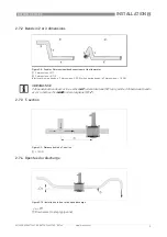
Page 9: ...ends upstream of the flowmeter 1 2 dimensions X Y 2 3 dimensions X Y Z Inlet length using bends in 2 dimensions t 5 DN when having bends in 3 dimensions t 10 DN INFORMATION 2 dimensional bends occur i...

Page 10: ...com 09 2020 4008472601 QS BATCHFLUX 3100 R01 en 2 7 5 Pump D 25 1 Drain valve to empty pipeline 2 7 6 Control valve D 25 1 Drain valve to empty pipeline Figure 2 11 Installation behind a pump Figure...

Page 11: ...7 7 Flange deviation Figure 2 13 Mounting position and flange deviation 1 Lmax 2 Lmin CAUTION Max permissible deviation of pipe flange faces Lmax Lmin d 0 5 mm 0 02 CAUTION Install the device always...

Page 12: ...2 14 Horizontal installation CAUTION Mount the flow sensor in such a way that the electrode axis X X is approximately in a horizontal pipe run Figure 2 15 No force on device after installing 1 After i...

Page 13: ...pipeline Figure 2 16 Installation in bending pipes CAUTION Install in a slightly descending pipe section of 25 degrees or larger to prevent air from collecting and to avoid faulty measurements meter...

Page 14: ...olts uniformly and in diagonally opposite sequence Do not exceed the maximum torque value Step 1 Apply approx 50 of max torque given in table Step 2 Apply approx 80 of max torque given in table Step 3...

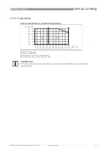
Page 15: ...3 Temperatures Process temperature vs ambient temperature 1 Ambient temperature 2 Process temperature 3 Temperature area for continuous process 4 Temperature area for cleaning up to 1 hour INFORMATION...

Page 16: ...ny work done on the electrical components of the measuring device may only be carried out by properly trained specialists INFORMATION Look at the device nameplate to ensure that the device is delivere...

Page 17: ...nd any other electrical device at the same conductor CAUTION When connecting to functional extra low voltages 24VDC ensure that you use protective separation PELV according to IEC 60364 IEC 61140 or V...

Page 18: ...types to connect the flowmeter to a third party system moulded plug straight or angle entry form integrally extruded plug with cable in various lengths moulded plug straight form especially suitable f...

Page 19: ...1 M12 5 pins connector Grounding 2 Grounding strip R radius mounting hole 4 3 mm 0 17 inch DN15 version with spacer bush 1 M12 5 pins connector Grounding 2 Grounding strip R radius mounting hole 3 1...

Page 20: ...g drawing to ensure that the device works correctly Dimensions Figure 4 1 Flange according DIN 11850 row 2 DIN 11866 row EN 10357 Serie A Figure 4 2 Flange according DIN 11850 row 2 DIN 11866 row EN 1...

Page 21: ...NOTES 5 21 BATCHFLUX 3100 C www krohne com 09 2020 4008472601 QS BATCHFLUX 3100 R01 en...

Page 22: ...5 NOTES 22 BATCHFLUX 3100 C www krohne com 09 2020 4008472601 QS BATCHFLUX 3100 R01 en...

Page 23: ...NOTES 5 23 BATCHFLUX 3100 C www krohne com 09 2020 4008472601 QS BATCHFLUX 3100 R01 en...

Page 24: ...g solutions Engineering commissioning calibration maintenance and training services Head Office KROHNE Messtechnik GmbH Ludwig Krohne Str 5 47058 Duisburg Germany Tel 49 203 301 0 Fax 49 203 301 10389...

Reviews: