background image

© KROHNE 

     7.30925.31.00


07.03.2003 

Installation and  
operating instructions 

BATCHFLUX 5015 K 

Compact electromagnetic 
flowmeters 

Please note! 
 

Do not open the housing of the BATCHFLUX IFM 5015 K. 

 
Danger of contamination with substances likely to destroy the 
moisture barrier of the electronic equipment (e.g. if CIP or SIP 
cleaned from the outside). 
 
Therefore, please contact your KROHNE Service engineer 
before you open the housing. 

Summary of Contents for BATCHFLUX 5015 K Series

Page 1: ...etic flowmeters Please note Do not open the housing of the BATCHFLUX IFM 5015 K Danger of contamination with substances likely to destroy the moisture barrier of the electronic equipment e g if CIP or SIP cleaned from the outside Therefore please contact your KROHNE Service engineer before you open the housing ...

Page 2: ...portant information 13 2 2 Attachment plugs 13 2 3 Power supply and outputs 14 3 Start up 15 16 3 1 Checking for availability 15 3 2 Factory settings 16 Part B IFC 015 signal converter 17 34 4 Operator control of signal converter with the HHT 010 17 27 4 1 Operator control concept 17 4 2 Operating and check elements 18 4 3 Function of keys 18 19 4 4 Table of settable functions 20 24 4 5 Error mess...

Page 3: ...nics unit 41 8 4 Restart 41 9 Illustrations of printed circuit boards 42 Part D Technical Data block diagram and measuring principle 43 49 10 Technical data 43 47 10 1 Flow during filling and fill volume 43 10 2 Flowmeters 43 10 3 Signal converter 44 10 4 Error limits at reference conditions 45 10 5 Dimensions and weights 46 47 10 6 Instrument nameplates 47 11 Block diagram 48 12 Measuring princip...

Page 4: ... certified Product liability and warranty The compact BATCHFLUX IFM 5015 K electromagnetic flowmeter is designed exclusively for measuring the volumetric flowrate of electrically conductive liquid process products The compact flowmeter is not suitable for use in hazardous areas Other flowmeter series are available for such applications Responsibility as to suitability and intended use of this comp...

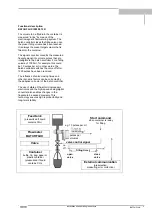
Page 5: ...ntroller switches the valve off after 1000 pulses have been received The influence of valve closing times and other dynamic factors can be corrected by the adaptive corrector of the batch controller The use of state of the art microprocessor electronics and the high speed analog digital converter also enables changes in the flowrate to be sensed precisely This technology ensures high reproducibili...

Page 6: ...DN and straight outlet run 2 x DN measured from the electrode axis DN meter size Vortex or corkscrew flow increase length of inlet and outlet runs or install flow straighteners Mixing different process liquids install flowmeter upstream of mixing point or at an adequate distance downstream minimum of 30 x DN DN meter size otherwise display may be unsteady Plastic pipes and internally coated metal ...

Page 7: ...not install flowmeter on pump suction side Open feed or discharge Install meter in low section of pipe open discharge Selecting the installation location Location and position as required but electrode axis X X must be approximately horizontal in a horizontal pipe run Direction of flow The red arrow on the primary head housing must point in the flow direction On high temperature pipes and where pr...

Page 8: ...ed when in installed condition During the cleaning the meter s must be switched off to maintain the reliability of the unit s Operating pressure type and space between pipe flanges see Table Tighten stud bolts uniformly down to the metal stop in diagonally opposed sequence See Table for type and number of stud bolts Install meter vertically or in a slope due to its conical in outlet On DN 15 1 2 a...

Page 9: ...e Sect 1 5 1 3 3 Grounding FE Functional ground wire 4 mm 2 Cu R Pipeline RF Pipe flanges V Interconnecting wires bolted to the housing All flowmeters must be properly grounded The grounding wire should not transmit any interference voltages Therefore do not ground any other electrical device simultaneously with this conductor Grounding is carried out via the functional ground that is connected to...

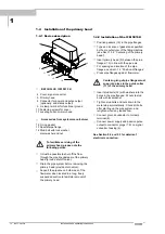
Page 10: ...ection to facilitate removal of the primary head 1 4 2 Installation of the IFM 5015 K Position gaskets 12 in the pipe flanges Type and location of gaskets as specified by the manufacturer of the filling machine see Sect 1 3 2 Centering of the primary head Insert primary head 5 between the pipe flanges 13 in line with the pipe axis For spacing and location of the pipe flanges see Sect 1 3 Position ...

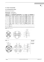
Page 11: ...on request 60 8 5 0 28 1 00 1 18 0 002 0 006 0 06 0 002 0 006 on request 2 36 0 33 6 1 4 9 25 5 30 0 05 0 15 1 5 0 05 0 15 on request 60 8 5 0 35 1 00 1 18 0 002 0 006 0 06 0 002 0 006 on request 2 36 0 33 10 3 8 12 25 5 30 0 05 0 15 1 5 0 05 0 15 on request 60 8 5 0 47 1 00 1 18 0 002 0 006 0 06 0 002 0 006 on request 2 36 0 33 15 1 2 14 25 5 30 0 05 0 15 1 5 0 05 0 15 Ø 16 5 60 8 5 0 55 1 00 1 1...

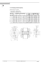
Page 12: ...6 0 002 0 006 on request 2 36 0 33 2 20 0 25 4 1 8 7 25 5 30 0 05 0 15 1 5 0 05 0 15 on request 60 8 5 56 6 4 0 28 1 00 1 18 0 002 0 006 0 06 0 002 0 006 on request 2 36 0 33 2 20 0 25 6 1 4 9 25 5 30 0 05 0 15 1 5 0 05 0 15 on request 60 8 5 56 6 4 0 35 1 00 1 18 0 002 0 006 0 06 0 002 0 006 on request 2 36 0 33 2 20 0 25 10 3 8 12 25 5 30 0 05 0 15 1 5 0 05 0 15 on request 60 8 5 56 6 4 0 47 1 0...

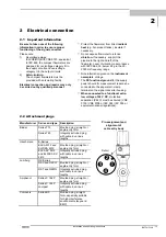
Page 13: ...ltage The FE functional ground for the supply power should for measurement reasons be connected to the separate U clamp terminal on the signal converter housing When connected to a functional extra low voltage of 24 V DC protective separation PELV must be ensured VDE 0100 VDE 0106 or IEC 364 IEC 536 or equivalent national regulations 2 2 Attachment plugs Manufacturer Series and type Description Bi...

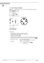
Page 14: ...3 2 factory settings Connection of electronic totalizers Digital pulse division Interpulse period non uniform therefore if frequency meters or cycle counters connected allow for minimum counting interval counter gate time s Hz P 1000 100 Pulse rate for Q 100 max 10 kHz fixed or optionally in pulses per m litres US gallons or user defined unit Pulse width 10 Hz 50 100 200 or 500 ms 10 Hz automatic ...

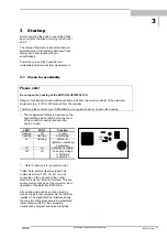
Page 15: ...The measurement status is signalled by the light emitting diodes LED below the cover of the converter housing see amplifier board on right LED 1 LED 2 Function flashing off in order flashing flashing overdriving on flashing Fatal Error defective operating parameter off on defective hardware off off no supply voltage or hardware is defective Refer to Section 6 for operator control Furthermore exter...

Page 16: ...ge of the low flow cutoff SMU or if separate displays and counts are required for both flow directions To avoid faulty measurements therefore it may be necessary to change the factory setting of some or all of the following functions low flow cutoff SMU Fct 1 3 pulse output P Fct 1 6 Function Setting 1 1 Full scale range Q100 see instrument nameplate 1 2 Time constant 3 s for S option 1 3 Low flow...

Page 17: ...ent e g if CIP or SIP cleaned from the outside Therefore please contact your KROHNE Service engineer before you open the housing Menu column Function column Data column 3 5 USER UNIT 3 4 ENTRY CODE 3 3 ZERO SET 3 2 FLOWMETER 3 0 INSTALL 3 1 LANGUAGE 2 2 HARDW INFO 2 0 TEST 2 1 TEST Q 1 7 IND OUTP S no HARDWARE 1 6 PULS OUTP P 1 5 CUR OUTP I no HARDWARE 1 4 DISPLAY 1 3 L F CUTOFF 1 2 TIMECONST 1 0 ...

Page 18: ...sor flashing part of display has a grey background in the following descriptions To start operator control Measuring mode Operator control mode PLEASE NOTE when YES is set under Fct 3 4 ENTRY CODE CodE 1 appears in the display after pressing key Now enter the 9 keystroke Entry Code 1 each keystroke acknowledged by To terminate operator control Press key repeatedly until one of the following menus ...

Page 19: ...t text Select previous text To transfer from text unit to number setting Change to number setting Return to text setting To transfer to subfunction Subfunctions do not have a Fct No and are identified by a To revert to function display 3 9 7 3 5 m 3 h r 3 9 7 4 5 m 3 h r 3 9 7 3 5 m 3 h r 3 9 7 3 5 m 3 h r 3 7 6 9 9 L i t e r S e c 9 3 3 6 5 U S G a l m i n 1 3 5 7 1 m3 h r 1 3 5 7 1 m3 h r 1 0 3 ...

Page 20: ...d reverse flow in F R mode Fct Text Description and settings 1 0 OPERATION Operations menu 1 1 FULL SCALE Full scale range for flowrate Q100 Select unit m 3 hr Liter Sec US Gal min user unit factory set is Liter hr see Fct 3 5 Press key to transfer to number setting Setting ranges The ranges are dependent on the meter size DN and the flow velocity v Qmin DN 2 x vmin Qmax DN 2 x vmax BATCHFLUX IFM ...

Page 21: ...NO YES cyclic change with meas value displays Press key to return to Fct 1 4 DISPLAY Fct Text Description and settings 1 5 CURRENT I Current output I No hardware available FUNCTION I Select function for current output I OFF must be set as hardware not available 1 DIR 1 direction of flow 2 DIR forward reverse flow F R flow measurement Press key to transfer to subfunction RANGE I RANGE I Select meas...

Page 22: ... No hardware available ALL ERROR FATAL ERROR OFF ON F R INDIC F R indication for forward reverse measurement TRIP POINT Setting range 002 115 PERCENT Press key to transfer to number setting Press key to return to Fct 1 7 STATUS S Fct Text Description and settings 2 0 TEST Test menu 2 1 TEST Q Test of range Q Precautionary query SURE NO Press key to return to Fct 2 1 TEST Q SURE YES Press key and s...

Page 23: ... Press key to transfer to subfunction GKL VALUE VALUE P Change pulse value see Fct 1 6 VALUE P Appears only when PULSE VOL has been set under Fct 1 6 SELECT P and the output frequency F has been over or undershot Pmin Fmin Q100 Pmax Fmax Q100 GKL VALUE Set primary constant GKL see instrument nameplate for primary head Range 1 0000 9 9999 Press key to transfer to subfunction FLOW DIR Fct Text Descr...

Page 24: ...quired unit for flowrate and counting TEXT VOL Set text for required flowrate unit max 5 characters Factory set Liter Liters Characters assignable to each place A Z a z 0 9 or blank character Press key to transfer to subfunction FACT VOL FACT VOL Set conversion factor FM for volume Factory set 1 00000 E 3 for Liter exponent notation here 10 3 Factor FM volume per 1m 3 Setting range 1 00000 E 9 to ...

Page 25: ...ounting during power failure Delete error message in RESET QUIT menu If necessary reset totalizer PULS OUTP P Pulse output overranged Note totalizer deviation possible Check instrument parameters and correct if necessary After cause has been eliminated error message is deleted automatically ADC Analog digital converter overranged After cause has been eliminated error message is deleted automatical...

Page 26: ...t delete error messages Press twice return to measuring mode QUIT YES Delete error messages ERROR QUIT Error messages deleted Return to measuring mode Reset totalizer s in RESET QUIT menu Key Display Description Measuring mode CodE 2 Key in Entry Code 2 for RESET QUIT menu ERROR QUIT Menu for error acknowledgement TOTAL RESET Menu for resetting totalizer RESET NO Do not reset totalizer Press twice...

Page 27: ...Installation and operating instructions 27 BATCHFLUX Notes ...

Page 28: ...ged full scale range Q100 the output frequency F of the pulse output is over or undershot Pmin Fmin Q100 Pmax Fmax Q100 Change pulse value accordingly see Sect 5 7 pulse output P Fct 1 6 5 2 Time constant Fct 1 2 TIMECONST Press key Selection ALL applies to HHT 010 display and all outputs ONLY I S only valid for HHT 010 display current and status outputs no current output no hardware Select with k...

Page 29: ...d values Select with keys and Press key to return to Fct 1 4 DISPLAY Note BUSY is displayed in the measuring mode when all displays are set to NO DISP and NO Sequencing of displays is automatic However in the measuring mode manual sequencing can be carried out with keys and Return to automatic sequencing after approx 3 minutes Please refer to Sect 3 2 Factory settings 5 5 Internal electronic total...

Page 30: ...tory settings Refer to Sect 2 3 for connection diagrams and to Sect 5 14 for characteristics 5 7 Pulse output P Fct 1 6 PULS OUTP P Press key FUNCTION P Select function for the pulse output press key OFF switched off no function 1 DIR 1 flow direction 2 DIR 2 flow directions F R mode forward reverse Select with keys and Transfer to subfunction SELECT P with key Exception when OFF selected return t...

Page 31: ...rsor 1 place to right or left with keys und Press key to return to Fct 1 6 PULS OUTP P or VALUE P Set pulse value per unit time appears only when PULSE TIME has been set under SELECT P press key XXXXX PulSe Sec max 10 kHz XXXX PulSe min XXXX PulSe hr XXXX PulSe user defined unit factory set is hr see Sect 5 12 Select with keys and Transfer to number setting with key 1st digit cursor flashes Set nu...

Page 32: ...ith key 1st digit cursor flashes Change flashing digit cursor with keys and shift cursor 1 place to right or left with keys and Press key to return to Fct 1 7 IND OUTP S Characteristics of Switch open Switch closed status output OFF no function ON e g operation indicator Power OFF Power ON F R INDIC Forward flow Reverse flow TRIP POINT Inactive Active ALL ERROR Error s No error s FATAL ERROR Error...

Page 33: ...been changed the output frequency F of the pulse output is over or undershot Pmin Fmin Q100 Pmax Fmax Q100 Change pulse value accordingly see Sect 5 7 Pulse output P Fct 1 6 GKL VALUE Set the primary constant GK press key 1 0000 9 9999 note information on instrument nameplate do not change setting Change flashing digit cursor with keys and Shift cursor 1 place to right or left with keys and Transf...

Page 34: ... Factor FT for time press key 3 60000 E 3 factory set is 3600 set Factor FT in seconds Setting range 1 00000 E 9 to 9 99999 E 9 10 9 to 10 9 Change flashing place cursor with keys and Shift cursor 1 place to right or left with keys and Press key to return to Fct 3 5 USER UNIT Factors for volume FM Factor FM volume per 1 m 3 Volumetric unit Text examples Factor FM Setting Cubic metres m 3 11 111 0 ...

Page 35: ...n by the arrow on the primary head signifies the opposite direction Set the status indication output to F R INDIC see Fct 1 7 Set the current and or pulse output to 2 DIR see Fct 1 5 and 1 6 subfunctions FUNCTION I and FUNCTION P 5 14 Characteristic of outputs P Pulse output P100 Pulses at Q100 full scale range QF 1 flow direction or forward flow in F R mode QR Reverse flow in F R mode Q100 Full s...

Page 36: ...rd of the signal converter see Sect 9 and connect to PC or laptop 3 Switch on the power 4 As described in the CONFIG directions change data parameters and measured values and or have them called up for display 5 Switch off the power 6 Remove the RS 232 adapter from the amplifier board 7 Replace the cover and tighten down the 4 screws Please refer to Sect 3 2 Factory settings 6 2 Operation via HHT ...

Page 37: ... but make sure that the measuring tube is completely filled with fluid Switch on the system and wait 15 minutes Press the following keys for zero measurement Key Displayed Description If YES is set under Fct 3 4 ENTRY CODE key in the 9 keystroke CODE 1 Fct 1 0 OPERATION 2x Fct 3 0 INSTALL Fct 3 1 LANGUAGE 2x Fct 3 3 ZERO SET CALIB NO CALIB YES 0 00 Flowrate set in displayed unit see Fct 1 4 DISPLA...

Page 38: ... opening the housing For this test a measured value can be simulated in the range of 110 to 110 percent of Q100 for set full scale range see Fct 1 1 FULL SCALE Power the system Press the following keys for this test Keys Displayed Description If YES is set under Fct 3 4 ENTRY CODE key in the 9 keystroke CODE 1 Fct 1 0 OPERATION Fct 2 0 TEST Fct 2 1 TEST Q SURE NO SURE YES 0 PERCENT Current pulse a...

Page 39: ... 8 character and a 10 character status code are stored under this function in each of 3 windows These 6 status codes will enable rapid and simple diagnosis of your compact flowmeter Power the system Press the following keys for display of the status codes Key Displayed Description If YES is set under Fct 3 4 ENTRY CODE key in the 9 keystroke CODE 1 Fct 1 0 OPERATION Fct 2 0 TEST Fct 2 1 TEST Q Fct...

Page 40: ...pans or similar receptacles should be kept ready and used to collect any residual liquids in the pipe system when dismantling the flowmeter 8 2 Removal from the pipe system Detach power line from attachment plug 8 on signal converter housing Disconnect grounding wire from U clamp terminal 9 on converter housing Detach status indication wire option from attachment plug 7 Remove air supply line unsc...

Page 41: ...ide Therefore please contact your KROHNE Service engineer before you open the housing 1 Cover signal converter 2 Gasket 3 Electronic unit signal converter 4 Housing signal converter 5 Primary head 7 Printed circuit board 8 Plug connector power supply and pulse output 9 U clamp terminal for functional ground 10 Fastening screws for cover 11 Guide collar primary head 12 O ring gasket 13 Special pipe...

Page 42: ... with precisely defined sealing faces centering devices and metallic stop face Electrical conductivity 5 µS cm 20 µS cm for demineralized cold water Ambient temperature Process temperature 25 to 40 C 13 to 104 F 60 to 140 C 76 to 356 F 25 to 60 C 13 to 140 F 60 to 60 C 76 to 140 F information on higher provided on request steam cleaning up to 150 C 302 F Temperature shock resistance Temperature ri...

Page 43: ... control via PC Options connected to the IMoCom interface Pulse output passive circuit Function All operating data factory set to your specifications connection of electronic totalizers digital pulse division interpulse period non uniform therefore if frequency meters counters connected allow for minimum counting interval gate time counter Hz P 1000 100 Pulse rate for Q 100 max 10 kHz fixed or opt...

Page 44: ...3 3 ft s F 0 4 of MV 1 mm s F 0 2 of MV 1 mm s 0 4 of MV 0 04 inch s 0 2 of MV 0 04 inch s Repeatability Filling time TF Standard deviation σ 1 5 s TF 3 s 0 4 3 0 s TF 5 s 0 2 5 0 s TF 0 1 Reference conditions similar to EN 29 104 Liquid product water 20 C 68 F Straight inlet outlet runs 10 DN 5 DN DN meter size Valve closing time variation 1 ms Flow velocity 1 m s 3 3 ft s Volumetrically wet cali...

Page 45: ...10 Meter size Diameter d1 Weight DN inches mm inches kg lb 2 5 1 10 6 0 24 1 6 3 6 4 1 6 7 0 28 1 6 3 6 6 1 4 9 0 35 1 6 3 6 10 3 8 12 0 47 1 6 3 6 15 1 2 14 3 0 56 1 6 3 6 10 option 4 x M6 bolt hole on both sides section M M M6 miniature circular connector flow direction series 713 4 pin option ventilation ...

Page 46: ...5 2 3 5 1 40 1 1 2 83 3 27 215 8 46 81 3 19 42 1 65 2 3 5 1 10 6 Instrument nameplates miniature circular connector series 713 4 pin 10 l Type designation Serial No Insulation class of field coils Protection category to IEC529 EN60529 Pressure rating flange class Electrode material platinum Measuring tube material Al2O3 aluminium oxide Meter size DN mm and inches Measuring range Primary constant 2...

Page 47: ... EEPROM 1 ECOPROM while all internal correction and calibration values are stored in EEPROM 2 Functional group 2 generates a pulsed electronically controlled direct current for the field coils of the primary head This group is electrically connected to functional group 3 Block diagram IFC 015 Functional group 3 consists of passive FET optocouplers to allow control of electronic and electromechanic...

Page 48: ...Thus the induced voltage is proportional to the mean flow velocity when the field strength is constant Inside the electromagnetic flowmeter the liquid passes through a magnetic field applied perpendicular to the direction of flow An electric voltage is induced by the movement of the liquid which must have a minimum electrical conductivity which is proportional to the mean flow velocity and thus to...

Page 49: ...ion of 4 4 5 1 1 3 2 Frequency output S pulse output P 2 3 3 4 4 5 7 1 6 Keyword Section No Fct No Function of keys 4 1 4 3 Functional description page 5 Function s 4 4 Functional ground FE 1 3 3 2 1 2 2 Function column 4 1 Functional check 7 1 ff hardware info 7 3 2 2 zero 7 1 3 3 measuring range 7 2 Full scale range Q100 4 4 5 1 1 1 3 2 G Gaskets 1 4 2 10 3 GKL values 4 4 5 11 3 2 Grounding 1 3 ...

Page 50: ...lumn 4 1 4 3 main menu column 4 1 4 3 measuring mode 4 1 4 3 submenu column 4 1 4 3 Reverse flow R 4 4 5 13 1 4 1 7 RS 232 adapter 6 1 Keyword Section No Fct No S S status output 2 3 2 4 4 5 7 1 7 Safety conductor PE 1 2 3 2 2 Scope of supply 1 3 Signalling cable A 1 3 4 10 4 Signal converter IFC 015 connection power 2 2 connection HHT 010 4 2 8 9 operator control 4 1 4 3 spare parts 9 error limit...

Reviews: